
User talk:Jgmoxness
Welcome[edit]
[1]jgmoxness or Special:Emailuser/Jgmoxness
See also:
Images of the Archimedean and Catalan Solids[edit]

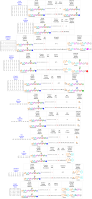
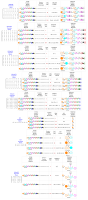
Images of maximal subgroup embeddings of Lie Algebras[edit]
- Images of maximal subgroup embeddings of Lie Algebras
-
 E8 Maximal Embeddings
 -
 E8 Maximal Embeddings with Weyl Orbits and Coxeter-Dynkin Diagrams
 -
 E7 Maximal Embeddings with Weyl Orbits and Coxeter-Dynkin
 -
 E6 Maximal Embeddings with Weyl Orbits and Coxeter-Dynkin
 -
 D8 Maximal Embeddings with Weyl Orbits and Coxeter-Dynkin Diagrams
 -
 C8 Maximal Embeddings with Weyl Orbits and Coxeter-Dynkin Diagrams
 -
 B6 Maximal Embeddings with Weyl Orbits and Coxeter-Dynkin Diagrams
 -
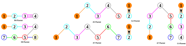
 A7 Maximal Embeddings with Weyl Orbits and Coxeter-Dynkin Diagrams
 -
 F4 Maximal Embeddings with Weyl Orbits and Coxeter-Dynkin
 -
 G2 Maximal Embeddings with Weyl Orbits and Coxeter-Dynkin


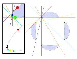
Images of Quartic Curves and Octonions as they relate to Electron Spherical Harmonic Legendre Functions and their Dual Quark-Gluon Nucleons[edit]
- Klein Quartic Curves
-
-

-


Images of Hasse Diagrams[edit]
- Hasse Diagrams
-
 F4 Hasse
 -
 E6 Hasse
 -
 E7 Hasse
 -
 E8 Hasse


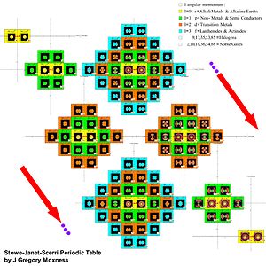
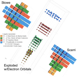
Images of Stowe-Janet-Scerri Periodic Table[edit]
- Stowe-Janet-Scerri Periodic Table organized by the Psi{n,l,+/-m} and +/-s quantum number symmetries and includes cutaway views of the spherical harmonics of the 3D orbital electron cloud probabilities.
-

-

-

-
-


Images of E8 (and its subgroups)[edit]
- E8 (and Subgroups) Visual Catalog of Regular Symmetries with Projections to 2D and 3D
-
 2D Polygons
 -
 3D Platonic Solids
 -
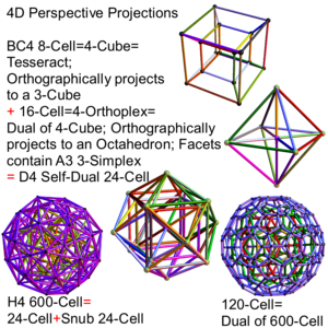 4D Polychora
 -
 5D Polytopes
 -
 6D Polytopes
 -
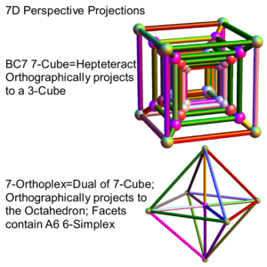 7D Polytopes
 -
 8D Polytopes


[edit]
- E8_(mathematics) and Quasicrystals
-
 6-cube (Hexeract) using 6D orthographic_projection to a 3D Perspective_(visual) object (the Rhombic_triacontahedron) using the Golden ratio in the basis_vectors (inner edges removed leaving their vertices).
 -
 6-cube (Hexeract) orthographically projected to 3D using the Golden ratio. This is used to understand the aperiodic icosahedral structure of Quasicrystals.
 -
 240 E₈ polytope vertices with 1440 6-cube (6D) unit edges and Golden ratio basis vectors orthographically projected to 3D.
 -

-
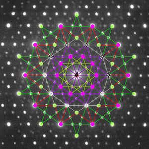 240 E₈ polytope vertices projected to 2D using 5-cube Petrie basis vectors overlaid on electron diffraction pattern of an icosahedral Zn-Mg-Ho Quasicrystal.


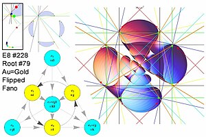
| E8 with Lisi Particle Assignments | ||||||
 Petrie Projection |
 E8 embedding |
 E8 embedding with particle labels |
 F4 (outer=Quarks, inner=Bosons/Leptons) w/Triality Edges |
 F4 with particle labels |
 Modified E6 projection showing Fermions in groups w/Boson rings |
 Mathematical representation of the physical Zome model isomorphic (?) to E8. |
| Hasse diagrams of selected E8 subgroups | ||||||
 A7 Hasse |
 F4 Hasse |
 C5 Hasse |
 D5 Hasse |
 E6 Hasse |
 E7 Hasse |
 E8 Hasse |
| Petrie Projections of the n-Cubes (C3 to C7, E8) | ||||||
 3D 4-cube |
 3-cube |
 4-cube |
 5-cube |
 6-cube |
 7-cube |
 E8 |
| Column (Pascal Triangle) Projections of the n-Cubes (C2 to C7, E8) | ||||||
 2-cube |
 3-cube |
 4-cube |
 5-cube |
 6-cube |
 7-cube |
 3D E8 |
| Coxeter Plane (Petrie) Projections of D3 to D8 | ||||||
 D3 |
 D4 |
 D5 |
 D6 |
 D7 |
 D8 in D7 |
 D8 |
| Coxeter Plane Projections | ||||||
 G2 |
 Cell 24 in D5 |
 Cell 24 in E6 |
 F4 in E6 |
 E6 |
 E7 |
 E8 in E6 |
| Cell 600 Projections | ||||||
 3D |
 Petrie |
 Square |
 Pentagon |
 Hexagon | ||
| Cell 120 Projections | ||||||
 3D |
 Petrie |
 Orthogonal |
 Pentagon |
 2Pi/3 basis | ||
| Other Projections | ||||||
 Rectified F4 with Triality |
 Birectified F4 |
 Rectified E8 with F4 Triality |
 E8 with 6720 Sqrt(6) edges |
 E8 in D8 | ||
Images Dynkin Diagrams[edit]
- Assorted Dynkin Diagrams
-
 Rank 3 Compact Hyperbolic Dynkin Diagrams (1-5 of 238)
 -
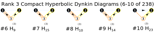 Rank 3 Compact Hyperbolic Dynkin Diagrams (6-10 of 238)
 -
 Finite Dynkin Diagrams
 -
 Affine Loop Dynkin Diagrams
 -
 Hyperbolic and very extended affine Dynkin Diagrams
 -
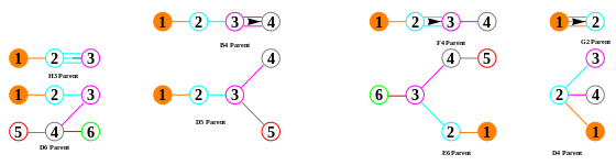 Folding Dynkin Diagrams
 -
 Folding Dynkin Diagrams
 -
-

-
-

-
-
-
-
-
-

-

-

-

-

-

-
-


|

|

|

| |||

|

|

|

| |||

|

|

|

|
Cell8+Cell16=Cell24
| Tesseract (Left frame orthogonal, Right frame perspective) |
Anaglyph for depth cueing(Red left eye, Cyan right eye) |
| Penteract
Hexeract |
Hepteract |
| 16 Cell | 24 Cell |
| 120 Cell | 600 Cell |
Images of Fano Planes[edit]
- Fano Planes.
-

-

-

-


Jgmoxness (talk) 02:52, 6 April 2010 (UTC)
What is wrong with this image?[edit]
On Talk:120-cell, you claimed that File:Cell120-4dpolytope.png is wrong. Can you please explain what is wrong with it? I admit that my caption for it may not have been the most accurate, but it cannot possibly be wrong (unless ALL of my other projections are wrong as well, since these images are all generated from the same underlying set of polytope data, differing only in the 4D and 3D projection viewpoints). If you think it's wrong because it doesn't match what you got with your own projection code, then please explain what exactly you did that led you to that conclusion - I suspect this is a case of unstated hidden parameters leading to different results. If you want, I can give you the precise projection parameters that I used to derive this image so that you can verify it for yourself.—Tetracube (talk) 22:38, 13 May 2010 (UTC)
- I agree (based on subsequent points made several months ago). We probably were simply using different basis vectors. What are the basis vectors you use for your projection?Jgmoxness (talk) 22:57, 13 May 2010 (UTC)
- Actually, I made a mistake; this image wasn't mine, but was posted by User:Tomruen. As far as its accuracy is concerned, you might want to be aware that this comes straight out of H. S. M. Coxeter's book, Regular Polytopes. While it's possible that he may have made a mistake, I would be very hesitant to question his accuracy unless there is ample proof to the contrary.—Tetracube (talk) 23:00, 13 May 2010 (UTC)
- No problem. I'm not questioning Coxeter (but wouldn't shy away if found wanting). It would be nice to know the what/how images are created - I publish as much code/data as desired in the image detail (or by request). Many authors don't. If you want more code/data for my stuff - let me know. Jgmoxness (talk) 23:10, 13 May 2010 (UTC)
- Actually, I made a mistake; this image wasn't mine, but was posted by User:Tomruen. As far as its accuracy is concerned, you might want to be aware that this comes straight out of H. S. M. Coxeter's book, Regular Polytopes. While it's possible that he may have made a mistake, I would be very hesitant to question his accuracy unless there is ample proof to the contrary.—Tetracube (talk) 23:00, 13 May 2010 (UTC)
- Well, I do eventually hope to get my code to the desired level of quality that I wouldn't be embarrassed to publish it (I am a firm believer in open source, after all), but Real Life has been unkind to me, especially when it comes to time---which is why I haven't been keeping up with all the discussions on 4D projections and stuff. In fact, I haven't even been able to finish a single new page on my website showcasing a uniform polytope of the 120-cell family, which I started, oh, almost 2 years ago? Besides that, I've been meaning to launch a "Polytope of the Day/Week/Month" thing on my website, to make it more appealing to visitors, but haven't gotten around to actually doing it yet. So you see, the real reason I've been shying away from doing the tesseract projection stuff when you asked was because I didn't want to get involved in yet another project that will demand more of my already limited time. I wasn't going to have another run-in with the WP:OR police and the deletionists, which is just extremely frustrating, exhausting, and unproductive.
- Anyway. The way I do projection for my images is a little more complex than what most people usually do (although in the end they can be interconverted with a suitable linear transformation, at least in theory). First I select a point in 4-space as a viewpoint, and then derive the hyperplane of projection as the 3-plane orthogonal to the vector from this point to the center of the polytope in question. Then 2 rotational angles within that 3-plane are selected as the "orientation" of the virtual 4D camera. Finally, the projection operator is applied, either using the parallel projection matrix or the perspective projection matrix. This yields a 5x5 projection matrix that maps the vertices to 3-space. Then, a different point, this time in 3-space, is selected as a second viewpoint, is used for generating the POVRay input file. There is no relation between the 4D viewpoint and the 3D viewpoint; the idea being that the first projection (4D->3D) represents what would happen in the eye of a hypothetical 4D creature looking at the polytope, whereas the second projection (done by POVRay) is merely a tool to help us poor 3D beings comprehend what the 4D being just saw. As such, the second projection can be done from any 3D viewpoint, as a way of exploring the same image captured by the 4D being's hypothetical retina.
- Furthermore, I also store my polytope data not only as vertices or hyperplanes, but as their full face lattices. It's true that the lattice can be computed directly from the vertices or hyperplanes, but doing so can be quite time-consuming (esp. for the more complex polytopes, like the 120-cell family polytopes and higher-dimensional polytopes), so I just compute them once and store them in the same file. Having the entire lattice available makes it possible to implement a rudimentary query language with which I can, say, center the viewpoint on a particular cell, face, or edge; color certain cells a certain way and their neighbours a different way, etc.. So this is how I generate my 4D projections.—Tetracube (talk) 23:28, 13 May 2010 (UTC)
- I (totally) know what you mean by publishing code and wanting the quality to be reflective of one's talent. I have spent 3 years on my e8Flyer.nbp (~1Mb source code) based in Mathematica. I have re-written it with significant attention to "quality" in case it were to be viewed by others. My approach is to define the vertex vectors based on the 256=240_E8+16_Ortho8. These are then projected to 2 or 3 dimensions with 2 or 3 basis vectors. If animated rotations are desired, then I insert 1-3 n-D rotation matrix dot-products. Jgmoxness (talk) 00:13, 14 May 2010 (UTC)
- Forgot to mention that I a completely agree with your point on "the WP:OR police and the deletionists, which is just extremely frustrating, exhausting, and unproductive." What is up with those self appointed gang of editors on the Tesseract page. I think the ensuing discussion on Talk:Tesseract was very helpful for me. Yet they still insist on not allowing it in the article even though it adds perspectives not available seems arrogant/ignorant. I suspect I may have tweaked their noses out of joint as I was upset at their inability to see the value of frame synchronized animations of 4D rotations to 3D isometric(parallel) and perspective projections. Maybe we can help each other through mutual support. I think they are less likely to reject additions if they come from someone other than the author. Maybe I can add some of your work - and see what they do?
- BTW - my approach to surfaces/faces (with or w/o POVray export from Mathematica) is not as good as yours. As you point out, it is compute intensive - and I haven't taken the time to optimize pre-compute and store the faces like do the vertices/edges. Thanks for the discussion - it is helpful. Jgmoxness (talk) 14:11, 14 May 2010 (UTC)
- I (totally) know what you mean by publishing code and wanting the quality to be reflective of one's talent. I have spent 3 years on my e8Flyer.nbp (~1Mb source code) based in Mathematica. I have re-written it with significant attention to "quality" in case it were to be viewed by others. My approach is to define the vertex vectors based on the 256=240_E8+16_Ortho8. These are then projected to 2 or 3 dimensions with 2 or 3 basis vectors. If animated rotations are desired, then I insert 1-3 n-D rotation matrix dot-products. Jgmoxness (talk) 00:13, 14 May 2010 (UTC)
- (outdent) Thanks, but to be honest, I rather spend my efforts on my own website.
- As for precomputing face lattices... After much study about how to visualize 4D objects, I have come to the conclusion that line drawings are fundamentally inadequate for capturing the information obtained by projecting a 4D object. They are easy to code, which is why just about every Java applet that does 4D projection uses line drawings. But ultimately, they are ambiguous, prone to illusory artifacts, and do not convey enough information to be insightful. That is why I rewrote my entire website to use POVRay to ray-trace transparent faces instead (believe it or not, all those pretty pictures used to be mere line drawings!). It took a lot of work, but was well worth it. My dream is to one day extend it to be able to handle non-convex objects and even multiple objects, and be able to render, say, 4D scenery. But whether or not I can reach that goal remains to be seen. :-)—Tetracube (talk) 17:56, 14 May 2010 (UTC)
- Quick reply, (not reading everything above). I made
 , originally in 1995 by a program I wrote to construct regular polytopes. It was uploaded as a gif, and converted to PNG by someone else apparently. Vertices and edges were constructed numerically by reflecting its vertex figure in 4-dimensional space. Its vertex figure is a tetrahedral pyramid. The height of the pyramid was computed so apex angle to two base vertices was 108 degrees of a pentagon face. The projection should be orthogonal, and it was positionally by manual rotation. There's probably lots of interesting orientations for projection that I've not seen. Lastly, sure, line-drawings are limited. If I remade this image, I'd also track overlapping edges/vertices to give some sense of what's hidden. Tom Ruen (talk) 04:54, 16 May 2010 (UTC)

- Thanks, Tom! If I recall, I was trying to recreate it using unit (orthogonal/orthonormal) basis vectors (e.g. {1,1,0,0}) and getting
 . I believe this was my (mistaken) original issue with it as "orthogonal". Subsequently, I found simple basis vectors of x=Normalize[{-3,-8,11,0}],y=Normalize[{11,-8,-3,0}] produces
  (which as you point out with the "manual rotation" fits your image perfectly. Originally, I did have a mistake in my 120-Cell construction (but had quickly corrected it). FYI - my images vertex colors vary with overlaps as:
 - vertices={{overlap,count},...,Total}
- {{{1,12},{3,108},{6,360},{9,108},{12,12}},600}
- vertices InView={{overlap,count},...,Total}
- {{{1,12},{3,36},{6,60},{9,12},{12,1}},121}
- Ultimately, I found a much more symmetric projection basis of x=Normalize@(2/13,-1/4,0,0), y=(0,0,1,0) giving ::

- Jgmoxness (talk) 15:51, 16 May 2010 (UTC)
- Thanks, Tom! If I recall, I was trying to recreate it using unit (orthogonal/orthonormal) basis vectors (e.g. {1,1,0,0}) and getting


- They look great, worthy variations to put on the article, but my preference (in these and other article images) would be (1) Suppress the black directional vectors, or add them as vectors to an image corner inside a small circle? (2) make all edges the same color (3) Color vertices by visual overlap (oh, they are? But we should pick some consistent coloring - my SVG have been red, orange, yellow... for sorted lo-to-hi order of overlaps), and (4) maximize the graphs to the SVG image extent. Tom Ruen (talk) 02:51, 18 May 2010 (UTC)
Dynkin diagrams[edit]
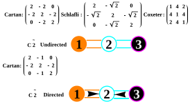
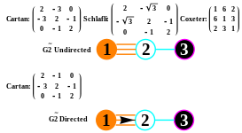
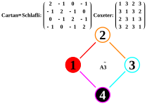
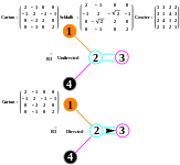
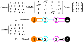
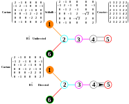
Hi Jgmoxness, On your diagrams like this one, there's a bit of confusion perhaps:

- The names you give correspond to ringed Coxeter-Dynkin diagrams, not directed Dynkin diagrams. (H3 and H4 are NOT Dynkin diagrams, only Coxeter because they're odd-ordered. n lines in Dynkins means order-2n, so 3 lines is 6 not 5, of H3/H4 Coxeter groups.) Coxeter groups are undirected, so no arrows, difference between Bn/Cn. Coxeter uses numbers on higher order edges rather than parallel lines, 4,5,6...
- Usually Coxeter diagrams are labeled starting with zero, so t0=regular, t1=rectified, t01=truncated, etc. Coxeter uses small SOLID dots for nodes for the Coxeter groups, and adds a ring around the dots for the truncation operators. Lastly he removes the central dot from ringed nodes as "holes" - alternated reflections ignored. So a snub is an omnitruncation (all nodes ringed), and all nodes alternated (holed). Your diagrams don't seem to distinguish between these 3 states - unringed, ringed, and holed.
- Also the operators, and only apply in the field of uniform polytopes. They have no meaning in other uses for these diagrams. Truncation names up to stericated are named by Norman Johnson, with truncation coming from Kepler's names of the 3D solids. They ought to be defined relative to the "zeroth" node. And things like "bi" prefixes mean shifted one step away from 0, like t0,1 is truncated, t1,2 is bitruncated, t2,3 is tritruncated etc. and t1=rectified, t2=birectified, etc. Most but not all are correct, but really ought to be given context as prefixes as operations on a regular polytope. Perhaps you now understand these operators are defining uniform polytopes, so they have vertices, edges, faces, cells, etc... Being uniform means all the edges are equal length, and all the elements are also uniform polytopes.
Have fun!
Tom Ruen (talk) 22:18, 23 December 2010 (UTC)
- Thanks for the attempt to clarify something that is for me (and most others) clear as mud (as we have discussed previously, e.g. while I was trying to determine how an n-cube label of Cn with n^2 vertices relates to a Lie Group of Cn with 2(n-1)) short roots and 2n^2 long roots). I am creating a GUI for inputing (Coxeter) Dynkin related diagrams as inputs to drive the E8 (and all of its A-H related subgroup) visualizations (which BTW includes all of the n-cubes). When I am ready to link a specific vizualization to a specific diagram, I will most likely try to follow all of the historical nuances of convention as you point out. Of course, I am not averse to creating a more consistent convention if that helps clear up some of this historically generated ambiguity.Jgmoxness (talk) 22:58, 23 December 2010 (UTC)
- Sounds good, but I object to claims of historically generated ambiguity. There is clarity here within each domain, so you must know which domain you're in (which I admit I'm not sure!) Tom Ruen (talk) 23:15, 23 December 2010 (UTC)
- p.s. If you want to have a good visual understanding of the symmetries, Jeff Week's application KaleidoTile is a good place [2]. Only "3d", but it shows a fundamental domain triangle where the generator point is placed, and all the archimedean solids come out of each symmetry, and there's degrees of freedom in the Kaleidescope, contiuous progression between the "equal edges" solutions. Tom Ruen (talk) 23:20, 23 December 2010 (UTC)
- I'm interested in your ambiguities. I'm not really sure what issues concern you. My interest is to defend consistent terminology, so if you call something X, it ought to be X, and not something else. Do you have a use for truncation terminology outside of uniform polytopes? And is is important to differentiate between directed and undirected graphs? If so, with Dynkin diagrams, 3 lines MEANS order-6, nothing else, and must be directed, like G2. There's no ambiguity. If you are interested in H4, then Coxeter diagram notation is the only game in town, and I see no reason to mix things that were intentionally separated for clarity. Tom Ruen (talk) 06:15, 24 December 2010 (UTC)
- Thanks Tom! This is helping clarify the mud in my minds eye. I too am concerned about X=X. As I pointed out earlier - a 32 root (vertex?) Lie Group Dynkin C4=C4 unless it is a Coxeter-Dynkin C4 (in which case it is a 16 vertex 4-cube). Of course, there is indeed a 4-cube inside E8 (which is both a Lie algebra/group and uniform polytope). This has the sound of the comedy sketch "Who's on first", which is at the heart of it a play on ambiguity. I have got to believe there have been many similar discussions in the history of hammering out all this hyperdimensional geometry stuff.
- Let me describe my (prior) perspective on this topic. It seems that it is topologically ok to flip diagrams around - so for G2 the arrow pointing left or right would not change the description of the root system. If true - why "MUST" G2 (or F4 for that matter) be "directed" if it doesn't change on left vs. right arrow ?? I have noticed the arrows for B&C (with n>2) either point into the other nodes or away from them (on the ends). If one were to force a left-right diagram convention- the arrows seem to become unnecessary. Of course, given the permutations of the Affine Dynkin diagrams - that would be more tedious - so keeping the arrows seems a good idea (plus they allow one to differentiate the Coxeter-Dynkin 3-line (order 5) notation of Hn polytopes from the 3-line (order 6) Dynkin diagrams (whatever they translate to??). I see that now.
- I was intrigued by your work with the Dynkin folding of the E8 to H4 (which I guess had issues?). This idea seems to be the link to the ideas of Richter who suggested that E8 is isomorphic to 2 concentric H4 scaled by the Golden Ratio. That is, by the way, the motivation behind the Zome model used on the E8 pages. I believe there is a deeper link in all this - and hope to tease it out and visualize it with push-button ease using my Mathematica software.
- Keep on correcting me, I need it (even if I may not "like it" ;-)Jgmoxness (talk) 16:45, 24 December 2010 (UTC)
- As for Coxeter's dots, rings and holes - the permutations of possibilities are binary operations from 1 to 2^rank. The parent being 1 (left (or right?) node "ringed" (or in my case filled). The 2^rank being "snub" (or all empty - consistent with the standard all holes). The 2^rank-1 is the "omnitruncated" all ringed (or in my case all filled). The only issue is whether to use dots and rings vs. empty and filled. Both uniquely determine the permutations. The code and GUI to generate all visualizations of both Dynkin AND Coxeter-Dynkin is more simple this way.Jgmoxness (talk) 17:18, 24 December 2010 (UTC)
- I'm interested in your ambiguities. I'm not really sure what issues concern you. My interest is to defend consistent terminology, so if you call something X, it ought to be X, and not something else. Do you have a use for truncation terminology outside of uniform polytopes? And is is important to differentiate between directed and undirected graphs? If so, with Dynkin diagrams, 3 lines MEANS order-6, nothing else, and must be directed, like G2. There's no ambiguity. If you are interested in H4, then Coxeter diagram notation is the only game in town, and I see no reason to mix things that were intentionally separated for clarity. Tom Ruen (talk) 06:15, 24 December 2010 (UTC)
- I'm sure Coxeter did "dot"+"ring" (ringing active mirrors) because he was drawing these by hand, but I think its more visually clear. I see you want to assign "no rings" as "snub", which by combination is sound, although there's alternations that are not all ringed, like


 is a cube and
  is an alternated cube (tetrahedron). The snub 24-cell has constructions from 3 families, and only the D4 family is a true snub, from all nodes holed.
 - I can't say much about the directed arrows in the Dynkin diagrams, and confirmed there are different conventions, but I tried to use the direct most agreed upon. And the problem is that there's the letter names in the affine groups, and reversing the direction is a completely different group, so easy to be confused, and following a consistent definition source seems essential for any communication.
- So basically Coxeter groups don't care about directed graphs because it makes no diference, so G2 is nothing special, just as well as I2(6). The only geometric difference I found is when the root systems are listed, the magnitude of the roots are different for the G2/Bn/Cn/F4 groups, so that means something, BUT for the polytope generation, only the direction of the roots is important, since they are simply normals to the reflective planes.
- Good luck on exploring the subsymmetries. I tried to sort them out from File:E8subgroups.svg and there's a close connection between these Lie algebra series and ABCD Letter names, but still a bit of a mystery to me. There's different colored lines, but no legend what they mean. Some are subsymmetries by node removal, and some are something else, some related to folding. Tom Ruen (talk) 23:31, 25 December 2010 (UTC)
- I expect you left off the undirected dual lines in these (per the templates):
- but the first Coxeter-Dynkin in the Tetrahedron differentiates from the cube consistently in my notation. As for the equivalency of the alternations in the tetrahedron - is that due to it being self-dual? (in other words, saying exactly the same thing as the first diagram)?Jgmoxness (talk) 00:43, 26 December 2010 (UTC)
- The Coxeter-Dynkin diagram represents a construction of a uniform polytope, so there are different constructions, and naming each shows how they can each be constructed from different symmetry groups. The alternation operator (including the snub) show half subsymmetry (d3 within bc3) within an original polytope. So in this arrangement the tetrahedron is actually an 3-demihypercube, and the 16-cell is a demitesseract, while higher forms are unique polytopes, like demipenteract. So this is more about the relationship of the BCn family and Dn, rather than self-duality. Tom Ruen (talk) 00:50, 26 December 2010 (UTC)
- p.s. The C8 diagram with bi- prefix is wrong, unless you're counting from the high index node?! Tom Ruen (talk) 00:50, 26 December 2010 (UTC)
- ok, I get it. My notation accounts for a full snub, but not partial "snubification" (not a full alternation). BTW - you were right, my code was off on the the 127 (not 126) C8 pattern.Jgmoxness (talk) 01:26, 26 December 2010 (UTC)
- Close, but maybe there are different ways the terminology is used. I say operationally snub = alternated omnitrucation, and there's no partial vs full alternation, since in all cases it is deleting half the vertices of an original polytope. (Names can still be funny, like a "snub tetrahedron" is an icosahedron (nonuniformly "colored"), and operationally is an alternated truncated octahedron, since truncated octahedron is an omnitrucated tetrahedron.) Tom Ruen (talk) 01:55, 26 December 2010 (UTC)
- Ok, we're into semantics. It seems you are saying snub is only full alternation (and there is no partial "snub", just partial alternation - which my nomenclature does not address). But to quote WP, "an Alternation_(geometry) (also called partial truncation, snub or snubification)". It would seem you are parsing a bit too much!Jgmoxness (talk) 02:36, 26 December 2010 (UTC)
- Yes, it is a mess if you look at all the ways terminology is used/misused. Truncation in Kepler's terminology reduces edges, so n-gon faces become 2n-gon faces. In general a truncation has a degree of freedom as a fraction of edge truncation and then a rectification can be seen as a full-truncation (so edges reduced to points). Finally alternation is a full-truncation (rectification) on half the vertices! Tom Ruen (talk) 02:43, 26 December 2010 (UTC)
- Close, but maybe there are different ways the terminology is used. I say operationally snub = alternated omnitrucation, and there's no partial vs full alternation, since in all cases it is deleting half the vertices of an original polytope. (Names can still be funny, like a "snub tetrahedron" is an icosahedron (nonuniformly "colored"), and operationally is an alternated truncated octahedron, since truncated octahedron is an omnitrucated tetrahedron.) Tom Ruen (talk) 01:55, 26 December 2010 (UTC)
- ok, I get it. My notation accounts for a full snub, but not partial "snubification" (not a full alternation). BTW - you were right, my code was off on the the 127 (not 126) C8 pattern.Jgmoxness (talk) 01:26, 26 December 2010 (UTC)
Very sorry to be a pain here, but is ![]()
![]()
![]()
![]()
![]() considered a full alternation (or truncation) or partial (which you just implied does not happen)? If it is full, wouldn't it be the same as my "full snub"
considered a full alternation (or truncation) or partial (which you just implied does not happen)? If it is full, wouldn't it be the same as my "full snub" ![]()
![]()
![]()
![]()
![]() ? confused again...Jgmoxness Jgmoxness (talk) 03:11, 26 December 2010 (UTC)
? confused again...Jgmoxness Jgmoxness (talk) 03:11, 26 December 2010 (UTC)
- My mistake, should have been [4,3] family above. From the [4,3] family, (


 ) it is an alternation, pure and simple, full/partial modifiers are senseless. Alternation means half the vertices are deleted. 8 vertices of cube become 4 of tetrahedron. It could be a snub cuboid perhaps (as a prismatic family), (
 ) as an alternated cuboid (
 ).
). - But from the [3,3] family, it means nothing () since the () has triangle faces, so it can't be alternated.
- Is that confusing enough? Tom Ruen (talk) 03:29, 26 December 2010 (UTC)
- So would you agree that since only one hole indicator is needed to show "snubification of omnitruncated polytopes", then it can be said that "all nodes as holes" is the same as "one hole" (both being "snub"). This would at least imply some level of consistancy between the traditional representations and my fundamentally binary representation- correct ?Jgmoxness (talk) 05:17, 26 December 2010 (UTC)
- Yes, a "zero-ringed" Coxeter-Dynkin diagram is a singular unused (as a degenerate case), and a snub (as an alternated omnitruncation) is a singular special case in need of a symbol, so assigning them together is a legitimate rule choice. In Coxeter-Dynkin diagrams specifically, an unringed diagram is given a special purpose, of representing the symmetry group itself (like Dynkin diagrams). But this approach is used in Wythoff symbols, with 8 symbols. Anyway, I'd say you can do as you like, but somewhat confusing. Perhaps you can called them Moxness diagrams and then you can define them as you like. Tom Ruen (talk) 23:35, 26 December 2010 (UTC)
Directed graphs[edit]
Hi Jgmoxness. On the issue of directedness, and if it matters, like G2, ![]()
![]()
![]() , the direction doesn't matter for the geometry, but for some reason affects the root vector magnitudes, like here:
, the direction doesn't matter for the geometry, but for some reason affects the root vector magnitudes, like here:  . So one node corresponds to the short vectors, one to the long ones. But in in terms of reflection symmetry, the magnitudes don't matter. The roots just represent normal directions to the reflection hyperplanes. Tom Ruen (talk) 22:02, 27 December 2010 (UTC)
- Thanks. It is interesting to note the reference on the bottom of the Dynkin diagram page
- [http://math.mit.edu/~lesha/dynkin-diagrams.html Web tool for making publication-quality Dynkin diagrams with labels
- This has nodes starting at 1 (not 0) and the G2 has the arrow consistent w/my diagrams. I know these don't REALLY matter, but they don't seem to be "hard rules".Jgmoxness (talk) 18:56, 28 December 2010 (UTC)
- Finite and affine Dynkin diagrams count from 1, but you'll see there are different conventions that the generator supports. The Coxeter-Dynkin diagram zero-node indexing comes from Coxeter's t-notation for listing the rings, t0 for end-node (usually regular), t0,1 for truncation etc. The only other use for indices is for identifying facets. Removing node (mirror) i expressed the facet polytope opposite in the fundamental simplex to that mirror. Tom Ruen (talk) 01:32, 29 December 2010 (UTC)
- p.s. The Johnson truncation names for uniform polytopes are only unambigously defined in linear diagrams, or subgraphs. They can be used operationally if the nodes are numbered, but lose a simple geometric meanings. It's not clear to me, your purpose in adding Coxeter rings to directed Dynkin diagrams. Tom Ruen (talk) 01:38, 29 December 2010 (UTC)
- Sometimes the perspective & questioning of the "outsider" can result in insights not easily seen by those "inside" because their world view has been fixed by "convention". If you're right, the Coxeter permutations may be meaningless or duplicative on directed graphs- not sure, as I am a bit naive here.
- My view of this is to construct a single user interface (with backend code) to drive visualizations of all possible geometric permutations of symmetries up to order 8. My Dynkin graph pic sets are simply Mathematica exports from the GUI I wrote (e.g. the set of Dynkin diagrams will be understood as crossed diagrams - 2 A1 diagrams on the screen is A1xA1). This gets you the prisms, etc. Of course, those pics with all the graphs are just visual examples.
- Since, I can:
- Algorithmically "recognize" and generate all the Dynkin topologies (not just "remember them" by hard coding)
- Apply all the symmetry projection basis vectors (not completely "algorithmically generated" yet - working on that)
- Recognize and drive the Coxeter (2^rank binary) permutations automatically
- Flexibly drive and generate visualizations and animations (2D & 3D) of any data set (even non-symmetric) of any dimension (within reason)
- It should be a simple matter to script the generation of the figures. Most of these are subsets of the E8 vertices (roots), which makes it even easier. This is similar to what you must be doing to generate yours (possibly manually). I would love to share ideas - as I am struggling on how to code the truncation algorithm in an elegant way (I think I have the rectifications). Would you be willing to share how you generate them? Jgmoxness (talk) 17:11, 29 December 2010 (UTC)

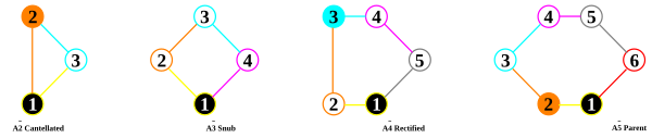
|

|
| These charts, containing the ideas from KalideoTile, showing the fundamental triangle, and generator point, and degrees of freedom. They are right triangles because of the linear CD. | |
- I've tried a few approaches, one using vertex figures (each must be computed), and second using systematic coordinates of the ABCD families, and third computing truncations from regular figures. The "real" general approach is to use the matrix of the "simple roots", compute the generating point inside the fundamental simplex, and perform recursive reflections across the hyperplanes normal to each root vector. So once set up, easy for finite forms. Affine/hyperbolic forms obviously need some limiting criteria to stop the recursion! Anyway that's why I suggested KalideoTile, since it described the general solutions and "snaps" to the uniform solutions. Basically every "ring" actually represents the distance from the mirror, zero or larger. Each ring generates one "edge-class" of the graph as the line between a point and its mirror image. So n-rings means n-degrees of freedom, and only one "uniform" solution that equalizes all edgelengths. I've only tested this in 3D, so I'd better code a general solution sometimes! Tom Ruen (talk) 22:01, 29 December 2010 (UTC)
- What method(s) and/or code are you using to generate your many geometric permutation figures?(e.g. Truncated 4_21 to A7)
- What method(s) and/or code are you using to generate your many geometric permutation figures?(e.g. Truncated 4_21 to A7)

- The Coxeter plane for A7 in 8-space comes from the 7-simplex facet of the 8-orthoplex, so basically projecting (1,0,0,...), (0,1,0,0,...) ... (0,0,...,1) points into 8-gonal symmetry. Tom Ruen (talk) 21:41, 30 December 2010 (UTC)
- Not sure I understand - wouldn't there only be 2 basis vectors to project the 7-simplex into 2D? How about the BC & Ds? Can you share (or email jgmoxness@theoryofeverything.org) code snippets related to truncation? (it would seem from the polyhedron truncation that each ring (or unring) operation is a truncation. This done repeatedly then generates rectifications and cantellations (correct?).Jgmoxness (talk) 21:49, 30 December 2010 (UTC)
- I don't know if I can explain any better by email. My main trick is given a sequence of vertices of a regular polytope, to project as a regular m-gonal Petrie polygon. So that sets up a system of equations as dot products: [dot(u,p(i),dot(v,p(i)]=[cos(2*pi*i/m),sin(2*pi*i/m)]. I solve for u,v vectors. I used that for the simplex and hypercube families. So the weakness of the trick is knowing the petrie polygon sequence. That's easy for a simplex since all vertices are used, so any order is a petrie polygon. A hypercube was easy, just a zig-zag path from one vertex n-steps towards its opposite. (For other basis, like Ak, sometimes I'd isolate regular k-simplex face of other polytopes, and then compute a uv Coxeter plane basis in that subspace, and map that uv basis back to the full space. Tom Ruen (talk) 22:32, 30 December 2010 (UTC)
- Ah, I think I am getting it. So you solve for the u,v vectors and get 2 vectors for any set of vertices being projected into that plane, right? The truncated 4_21(E8) above projected to the A7 Coxeter plane is looking 8-gonal(m=8). So you are then assigning the identity of the A7 Coxeter plane for ALL(?) m=8-gonal symmetries using that derivation. I put in a question mark because it seems the naming is not consistent across all your images (e.g. do you use the same Cos/Sin equation (with a given m) in other Coxeter plane IDs (BCn or Dn?) or are those different equations? if so, can you share?). Since you don't publish the basis vectors with each image like I try to do, it is harder to tell. I am getting for the above
- u={0.707, 0.5, 0., -0.5, 0., 0., 0., 0.}, v={0., 0.5, 0.707, 0.5, 0., 0., 0., 0.}
- or alternatively, but producing the same image for E8,
- u={0.5, 0.353553390593, 0., -0.353553390593, -0.5, -0.353553390593, 0., 0.353553390593}
- v={0., 0.353553390593, 0.5, 0.353553390593, 0., -0.353553390593, -0.5, -0.353553390593}
- This cos(2*pi*i/m),sin(2*pi*i/m) pattern only gets the simple fractions of 2Pi projection vector pairs up to 16 - listed as B8(16/2) on the 4_21_polytope page

- I initially thought u,v above would be listed as A7 on the 4_21_polytope page
- I initially thought u,v above would be listed as A7 on the 4_21_polytope page
 )
)
- But my calculation of the E8 image for this pair of basis vectors gives
- But my calculation of the E8 image for this pair of basis vectors gives
 with less overlap complexity of:
- InView vertices={{overlap,count},...}Total
- {{1,24},{8,24},{24,1}}49
- All vertices={{overlap,count},...}Total
- {{1,24},{8,192},{24,24}}240
- and seems to be listed as the 8 D5/B4 symmetry on the 4_21_polytope page

- So I guess I am still confused about the difference between the derivation of A7 & B4/D5 (both order 8). Of course, beyond these are the not-so-simple (u,v) symmetry vector pairs which have multiple orbits lengths. You may recall I gave you these special basis vectors from what Madore gave me (the 18(E7), 20 & 24-gonal) or I found myself (with help from Lisi) (the 6(F4), 12(E6), & 30(E8)-gonal) and you've used them extensively for your projections.
- That would cover all the symmetries, right? (or are there any other basis vector pairs you've found?)
You're right, I ought to encode the basis in the SVG file as XML comments. My last round I encoded comments listing the vertex overlap orders at least.
Sorry, which question on method of truncating?
For the e8 family, I show "global" Bk=D(k+1) bases from the 8-cube, and "local" Ak bases from one 7-simplex facet of the 4_21 polytope. So here's what I have for E8. Tom Ruen (talk) 23:36, 31 December 2010 (UTC)
// GLOBAL BCn=D(n+1) computed from petrie polygons from 10-cube
// BC2
  v1c2=(1,0,0,0,0,0,0,0,0,0)
  v2c2=(0,1,0,0,0,0,0,0,0,0)
// BC3
  v1c3=(0.408248290464,0.816496580928,0.408248290464,0,0,0,0,0,0,0)
  v2c3=(-0.707106781187,0.000000000000,0.707106781187,0,0,0,0,0,0,0)
// BC4
  v1c4=(0.270598050073,0.653281482438,0.653281482438,0.270598050073,0,0,0,0,0,0)
  v2c4=(-0.653281482438,-0.270598050073,0.270598050073,0.653281482438,0,0,0,0,0,0)
// BC5
  v1c5=(0.195439507585,0.511667273602,0.632455532034,0.511667273602,0.195439507585,0,0,0,0,0)
  v2c5=(-0.601500955008,-0.371748034460,0.000000000000,0.371748034460,0.601500955008,0,0,0,0,0)
// BC6
  v1c6=(0.149429245361,0.408248290464,0.557677535825,0.557677535825,0.408248290464,0.149429245361,0,0,0,0)
  v2c6=(-0.557677535825,-0.408248290464,-0.149429245361,0.149429245361,0.408248290464,0.557677535825,0,0,0,0)
// BC7
  v1c7=(0.118942442321,0.333269317529,0.481588117120,0.534522483825,0.481588117120,0.333269317529,0.118942442321,0,0,0)
  v2c7=(-0.521120889170,-0.417906505941,-0.231920613924,0.000000000000,0.231920613924,0.417906505941,0.521120889170,0,0,0)
// BC8
  v1c8=(0.097545161008,0.277785116510,0.415734806151,0.490392640202,0.490392640202,0.415734806151,0.277785116510,0.097545161008,0,0)
  v2c8=(-0.490392640202,-0.415734806151,-0.277785116510,-0.097545161008,0.097545161008,0.277785116510,0.415734806151,0.490392640202,0,0)
//B9
  v1c9=(0.081858535979,0.235702260396,0.361116813613,0.442975349592,0.471404520791,0.442975349592,0.361116813613,0.235702260396,0.081858535979,0)
  v2c9=(-0.464242826880,-0.408248290464,-0.303012985115,-0.161229841765,0.000000000000,0.161229841765,0.303012985115,0.408248290464,0.464242826880,0)
//B10
  v1c10=(0.069959619571,0.203030723711,0.316227766017,0.398470231296,0.441707654031,0.441707654031,0.398470231296,0.316227766017,0.203030723711,0.069959619571)
  v2c10=(-0.441707654031,-0.398470231296,-0.316227766017,-0.203030723711,-0.069959619571,0.069959619571,0.203030723711,0.316227766017,0.398470231296,0.441707654031)

// LOCAL Ak from 4_21 computed from petrie polygons in one 7-simplex
//A2 (Same view as BC3)
  v1a2=(0.000000000000,-1.000000000000,0.500000000000,0.500000000000,0.000000000000,0.000000000000,0.000000000000,0.000000000000)
  v2a2=(-0.000000000000,0.000000000000,-0.866025403784,0.866025403784,0.000000000000,0.000000000000,0.000000000000,0.000000000000)
//A3 (Same view as BC2)
  v1a3=(-0.000000000000,-1.000000000000,0.000000000000,1.000000000000,-0.000000000000,0.000000000000,0.000000000000,0.000000000000)
  v2a3=(0.000000000000,0.000000000000,-1.000000000000,0.000000000000,1.000000000000,-0.000000000000,0.000000000000,0.000000000000)
//A4 (Same view as BC5)
  v1a4=(0.000000000000,-1.000000000000,-0.309016994375,0.809016994375,0.809016994375,-0.309016994375,0.000000000000,0.000000000000)
  v2a4=(0.000000000000,-0.000000000000,-0.951056516295,-0.587785252292,0.587785252292,0.951056516295,0.000000000000,0.000000000000)
//A5
  v1a5=(-0.000000000000,-1.000000000000,-0.500000000000,0.500000000000,1.000000000000,0.500000000000,-0.500000000000,-0.000000000000)
  v2a5=(0.000000000000,-0.000000000000,-0.866025403784,-0.866025403784,-0.000000000000,0.866025403784,0.866025403784,0.000000000000)
//A6 (Same view as BC7)
  v1a6=(-0.000000000000,-1.000000000000,-0.623489801859,0.222520933956,0.900968867902,0.900968867902,0.222520933956,-0.623489801859)
  v2a6=(0.000000000000,-0.000000000000,-0.781831482468,-0.974927912182,-0.433883739118,0.433883739118,0.974927912182,0.781831482468)
//A7
  v1a7=(0.353553390593,-1.353553390593,-1.060660171780,-0.353553390593,0.353553390593,0.646446609407,0.353553390593,-0.353553390593)
  v2a7=(-0.353553390593,0.353553390593,-0.353553390593,-0.646446609407,-0.353553390593,0.353553390593,1.060660171780,1.353553390593)
- This is great ! It really helps. I took the A7 projection (very interesting) and simplified it to:
- u=(1, -1 -2 Sqrt[2], -3, -1, 1, 2 Sqrt[2] - 1, 1, -1)
- v=(-1, 1, -1, -2 Sqrt[2] + 1, -1, 1, 3, 1 + 2 Sqrt[2])
- BTW - it is interesting to note that this projection is effectively the same as what would be expected of the normal A7, except that one vector position x>4 needs to be asssigned to be the same as the x-4th position.
- giving:
- u=(Sqrt[2], 1, 0, -1, Sqrt[2], -1, 0, 1)
- v=(0, 1, Sqrt[2], 1, 0, -1, -Sqrt[2], -1)

- Also, I found the A5 is the same view as the BC3=D4, so the A7 is the only new projection (right? - not sure if by "local" it means there are different Ak for different vertex groups).
- My question about the truncation operation is to understand the generic algorithm for applying a ring (or un-ringing) a Dynkin node. What method (code) do you use to get the higher dimensions truncated based on the Coxeter Dynkin ringed nodes?Jgmoxness (talk) 19:10, 1 January 2011 (UTC)
- I didn't find A5 same view as BC3=D4, as seen at List of E8 polytopes, but A2 was the same! "Local" just means not necessarily aligned in a predictable way with coordinate axes. I am concerned, since there are potentially many of these subsymmetry views. Every "edge" in the E8 Coxeter graph technically defines a potential tetrahedron, with its own A2 Coxeter plane. I'd expect if all 255 polytopes were generated, that some would have different unique projections in different A2 planes. And same for A3, A4, A5. But given most have too many vertices to draw, perhaps they will never be seen (okay highest omnitruncation has 696,729,600 vertices), ALTHOUGH a smarter algorithm could accumulate specially symmetry projections without storing all the vertices!
- On "truncation" question, so I haven't implemented the general solution, which is silly, might be easier, but so far for "exceptional families" I've just worked from regular forms. Rectification=vertices at midedges, birectified=mid-faces, tri-rectified=mid-cells, etc. Then truncation creates two vertices on edges, positions based on the number of sides of the connecting face. (Triangle divides into 1/3s, square is like 1/(1+sqrt(2)) or something like that - you can compute it from a truncated cube). I did some quick tests for cantellation, and cantruncations, again extracting from uniform polyhedra proportions. But really this all should be computed directly from the simple roots matrix. I've just been lazy, using code I already had, and adding bits at a time. Tom Ruen (talk) 05:30, 2 January 2011 (UTC)
- ok, rechecked the A5 & BC3=D4 (not sure why I thought they were the same, but they do derive from the similar simple fractions over Pi or 2Pi)...
- I understand the basics of the truncation/rectification/etc. Are you saying (for example), when you calculated the Bisteriruncicantitruncated 7-simplex
 that it is a unique algorithm from each of the hundreds of images you've done and each is coded manually considering each Coxeter Dynkin permutation?? It seems hard to believe (unless the "code I already had" is at least somewhat "generic" related to the rings)?Jgmoxness (talk) 06:24, 2 January 2011 (UTC)

- Nope. I used coordinate permutations for the simplex and hypercube families. The n-simplex family is generated as positive orthant coordinate facets of the (n+1)-hypercube polytopes. That's what the "basepoint" columns are about, like at Uniform_polyexon#The_A7_family). User:Tetracube got those started. I only extended the pattern for the n-demicubes. Tetracube also computed them for F4, so I generalized that based on rings (at Uniform_polychoron#Coordinates_3). So its just the Exceptional group symmetries - H3/H4/E6/E7/E8 that need simple root reflections. Tom Ruen (talk) 07:30, 2 January 2011 (UTC)
- Well, I guess THAT code to take the basepoints and generate the projection is what I meant by "generic" (of course, w/o having known what you just said about the basepoint columns ...) I am trying to not "reinvent the wheel" - so if you can show me some code (now that I have a reference to what the basepoint data is used for - it would be MUCH easier to understand (for me, anyway). I can probably help finish the Exceptional group symmetries, if I can understand more about what you're doing. Of coure, if you don't want to share it - please just say so and I'll stop bothering you about it. Jgmoxness (talk) 15:26, 2 January 2011 (UTC)
I find reading my own code difficult enough, much less trying to decode someone else's, but here it is, from my "hypercube truncation" generator. Does it make any sense to you? Tom Ruen (talk) 16:52, 2 January 2011 (UTC)
  type
  fp=double;
  indexlist=array[1..maxdim+1] of byte;

var
  sum:array[1..maxdim] of fp;
procedure addverticesbypermuting(var index:indexlist; start,n:integer; half:boolean);
var i,j,k,temp,dim,c,cneg:integer;
  ok,done:boolean;
  sign:array[1..maxdim] of integer; // 0,-1,+1
  dist,mindist:fp;
  vv:vector_type;
begin
//mindist:=1e9;
dim:=n;
// quick test - require sorted permutations if equal coordinates
ok:=true;
for j:=1 to dim-1 do
  for k:=j+1 to dim do
  if (sum[index[j]]=sum[index[k]])
    and (index[j]>index[k]) then begin
//        writeln('perm ',i,' - no!');
      ok:=false; break;
      end;
if ok then begin // UNIQUE!
  for j:=1 to dim do sign[j]:=integer(sum[index[j]]>0);
  done:=false;
  c:=0;
  repeat
    inc(c);
    cneg:=0;
    if half then begin // suppress "odd" sign combinations?
      for j:=1 to dim do
        if sign[j]<0 then inc(cneg);
      end;
    if not half or (c mod 2=0) then begin
//      write('Signs[',c,']: ');
//      for j:=1 to dim do write(sign[j],' ');
//      writeln;
      trunccube.numverttotal:=trunccube.numverttotal+1;
      vv.init(dim);
      for j:=1 to dim do
        vv.el[j]:=sum[index[j]]*sign[j];
      if trunccube.numvert>0 then begin
        dist:=trunccube.vert[1].dist2(vv);
//        if dist<mindist then mindist:=dist;
        if (dist<4.01) then inc(trunccube.numedgeorder);
  //      writeln('dist=',dist:0:4);
        end;
      if trunccube.numvert<maxvert then begin
        inc(trunccube.numvert);
        if (trunccube.numvert mod 1000=0) then write('v',trunccube.numvert,'    ',^m);
        trunccube.vert[trunccube.numvert].copy(dim,vv);
        end;
      end;
// increment next binary permutation of signs...
    j:=1;
    repeat
      while (j<dim) and (sign[j]=0) do inc(j);
      if sign[j]=0 then begin done:=true; break; end;
      sign[j]:=-sign[j];
      if sign[j]=-1 then break;
      inc(j);
      done:=j>dim;
      until done;
    until done;
//  writeln(trunccube.numvert,') ');trunccube.vert[trunccube.numvert].print; writeln;
  end;
// NEXT!
if start < dim then begin
  for i:= dim-1 downto start do begin
    for j:=i+1 to dim do begin
      temp:=index[i];
      index[i]:=index[j];
      index[j]:=temp;
      addverticesbypermuting(index, i+1, n,half);
      end;
    temp:=index[i];
    for k:=i to dim-1 do
      index[k]:=index[k+1];
    index[dim]:=temp;
    end;
  end;
end;

procedure buildcube(n:integer; code:string; quick:boolean; var circumrad:fp); // truncated n-cube, code=n-digit binary number as a string of 0 or 1 characters.
var dim,i,c,j:integer;
  index:indexlist;
  k,mindist,dist:fp;
  cent:vector_type;
begin
dim:=n;
k:=sqrt(2);
for i:=1 to dim do sum[i]:=0;
sum[n]:=0;
if code[1]='1' then sum[n]:=1;
for i:=n-1 downto 1 do
  sum[i]:=sum[i+1]+ord(code[dim+1-i]='1')*k;
//write('Coord: ');
//for i:=dim downto 1 do write(' ',sum[i]:0:3);
//writeln;
trunccube.numvert:=0;
trunccube.numedge:=0;
trunccube.numverttotal:=0;
trunccube.numedgetotal:=0;
trunccube.numedgeorder:=0;
for i:=1 to dim do index[i]:=i;
addverticesbypermuting(index,1,n,false);
...
end


procedure buildDemicube(n:integer; code:string; quick:boolean; var circumrad:fp); // truncated n-demicube, code[1]=demicube, code[n]
// code[]=binary pos: n...54321
//        /-1
// 5-4-3-2
//        \-n
// code[1]=1, code[n]=0 needed for all unique demicube truncations
var dim,i,c,j:integer;
  index:indexlist;
  k,mindist,dist:fp;
  cent:vector_type;
  half:boolean;
begin
dim:=n;
k:=sqrt(2);
for i:=1 to dim do sum[i]:=0;
sum[n]:=0;
if (code[1]='0') and (code[n]='1') then begin code[1]:='1'; code[n]:='0'; end; // swap
half:=(code[1]='1') and (code[n]='0');
if half then begin sum[n]:=sqrt(2)/2; sum[n-1]:=sqrt(2)/2; end
else if code[n]='1' then sum[n-1]:=k;
for i:=n-2 downto 1 do
  sum[i]:=sum[i+1]+ord(code[dim-i]='1')*k;
//write('Coord: ');
//for i:=dim downto 1 do write(' ',sum[i]:0:3);
//writeln;
trunccube.numvert:=0;
trunccube.numedge:=0;
trunccube.numverttotal:=0;
trunccube.numedgetotal:=0;
trunccube.numedgeorder:=0;
for i:=1 to dim do index[i]:=i;
addverticesbypermuting(index,1,n,half);
....

end;
- Great - thanks for sharing. You may be right, the code is a bit cryptic. So I understand, this takes as input the basepoint index as a list and the n-cube start number (and boolean True if demicube) then generates the vertices to calculate edges from and project to a Coxeter plane given the basis vectors(?). Cool!
- BTW - here is copy/paste of the Mathematica (cell) code to set up the simple Coxeter plane basis vectors (these are padded with zeros up to the number of dimensions (8 for most of my E8 & its subgroups work on Lisi physics models).
(* do2PiCube@n=An-1=BCn(even)/2=Dn(even)/2+1
The A7 (n = 8) needs to have one m+4 index to overlap the m index (instead of no overlap),
and on order 8 vertices the ABCD \[Pi]=2\[Pi] symmetry is broken on n-odd>7 and beyond 16 *)

do2PiCube@n_:={
  H=Join[Table[Cos[(i-1)2\[Pi]/n],{i,Min[dims,n]}],
      Array[0 &, Max[0,dims-n]]],
  V=Join[Table[Sin[(i-1)2\[Pi]/n],{i,Min[dims,n]}],
      Array[0 &, Max[0,dims-n]]]}

(* creates the A7 style - plus any offsets *)
do2PiCubeAlt[n_, m_, offset_]:={
  H=Join[Table[Cos[(i-1)2\[Pi]/n], {i,Min[dims,n]}],
       Array[0 &, Max[0,dims-n]]]+offset; H[[m+4]]=H[[m]]; H,
  V=Join[Table[Sin[(i-1)2\[Pi]/n], {i, Min[dims,n]}],
       Array[0 &, Max[0,dims-n]]]-offset; V[[m+4]]=V[[m]]; V}
Foldings[edit]
Note: As you surely know, H3, H4 are not Lie groups and have no Dynkin graphs. 3 line connections represent an undirected order-6 graph. Tom Ruen (talk) 20:32, 3 January 2011 (UTC)
Also, doesn't seem like there should be any marked-nodes in these graphs, no "parent". Tom Ruen (talk) 20:42, 3 January 2011 (UTC)
- I get it and apologize for offending your accurate sensibilities, but as I was trying to explain...
- I am integrating multiple concepts into one UI and these are simply outputs from the s/w trying to recognize any type of graph input (whether it be Coxeter, Dynkin, Lie, affine, geometrically permuted, or...)
- Therefore they may contain inconsistencies in form related to current standards.
- It is also interesting that indeed E8 contains within it's structure undirected graphs for the n-cubes. It is also interesting WRT H4 - it seems to be strongly related to the E8 Lie group (by isomorphism and folding) as discussed by Richter et. al. Building on physics models from Lisi, I actually have a mapping between E8 and H4+H4/Phi that helps describe a possible integration of Relativity and Quantum Mechanics (similar to, but not the same as - string (or M) theory) - culminating in a ToE. Kinda cool! (and no, it is not ready for WP yet). Jgmoxness (talk) 22:02, 3 January 2011 (UTC)
- I guess my main question is what VALUE you have for directed Dynkin graphs? For geometry there's no value at all that I can see. It's only when you go to the related lie algebras that that directedness has a meaning. So why not abandon the directed graphs and stick with the Coxeter groups exclusively? Tom Ruen (talk) 22:22, 3 January 2011 (UTC)
- Thank you - I really do appreciate your interest. In addition to the geometry aspects of my work, I am also doing work that is INDEED related to the Lie Algebras (and its directed graphs as well as the undirected graphs). Now you are probably right and I will run into ambiguities trying to do geometric permutations on the directed graphs, but I still want to drive my s/w system using them as they relate to E8. For example, the E8 subgroups of the directed B and C (and G2) have different members (with long and short root combinations that may be meaningful to show). I also suspect there is a strong relationship in the D4 (24 cells & duals) and F4 with triality. It may be the directedness is a key to integrating the theories. It's all good - just trying to understand the Universe here.Jgmoxness (talk) 22:29, 3 January 2011 (UTC)
- BTW - Given that G2 Lie is a directed order 6 graph (as you pointed out originally above), is there a use for an "undirected order 6 link" in any Dynkin graph? (and if not, assuming undirected 3 lines equates to the H3 & H4 order 5)?
- You may want to comment on the A7 to ?2 graph with 4 lines. I suspect it is nonsense - but what are your thoughts on that folding option? Jgmoxness (talk) 22:47, 3 January 2011 (UTC)
- The Dynkin diagram article talks about directed and undirected Dynkin graphs. I've thought about making undirected Dynkin elements as I'm enumerating the noncompact hyperbolic graphs, since all permutations of directions are valid graphs, so it would make a shorter listing to ignore that. (BUT I can imagine a mixed-notation: since single-line=order-3, then double undirected line could imply order-5, and triple undirected line order-7, etc.) Tom Ruen (talk) 22:55, 3 January 2011 (UTC)
- On rank 2 graphs, undirected, Coxeter's bracket notation suffices: [p]=2-nodes, order-p edge. So A2=[3], B2=C2=[4], H2=[5], G2=[6], and order-8 is just [8], no associated letter. Or perhaps in group notation: [p]=I2(p). (But for a directed graph, there's no letter names. Apparently ignored since order-8 doesn't propagate to affine groups, only hyperbolic ones.) Tom Ruen (talk) 22:59, 3 January 2011 (UTC)
- ps I confirmed Dynkin diagrams are limited to 2,3,4,6 sides, as zero,one,two,three line branches. There'a also two affine (infinite) branches too (double-arrow&2-lines, and directed 4-lines). So for clarity I listed these in a table at Dynkin_diagram#Related_classifications. So no order-8 at all, even if useful in hyperbolic families, AND I assume directed order-8 branches could be studied as far as I know. I've listed all the compact and noncompact hyperbolic Coxeters groups now at Coxeter-Dynkin_diagram#Hyperbolic_Coxeter_groups. The Dynkins listing of noncompact hyperbolic diagrams is finite since limited to order-6. ANYWAY, I thought this would be useful for your notational diagrams. Tom Ruen (talk) 06:04, 6 January 2011 (UTC)
Quasicrystals(talk)[edit]
[13] I am afraid that for most visitors the joke might be lost . — Preceding unsigned comment added by 195.96.229.83 (talk) 13:11, 8 February 2012 (UTC)
A pie for you![edit]

|
well done Mai-Thai (talk) 16:43, 30 July 2012 (UTC) |
Root posets seem incorrect for type E[edit]
The Hasse diagrams for root posets of types E6, E7, E8 seem incorrect. In general, the elements of height 2 should be in bijection with the edges of the Dynkin diagram, because the sum of 2 simple roots is a root if and only if their corresponding vertices are connected by an edge of the Dynkin diagram. But, for example the graphic for type E7 (http://en.wikipedia.org/wiki/File:E7Hasse.svg) we see only 5 elements at height 2 instead of 6. The same problem appears for E6 and E8. I'm sorry that I don't know how to produce corrected versions of your nice graphics. SAGE can produce them, but they are unreadable in the default settings and I don't know how to adjust the parameters of the graphics.
P.S. I hope this is the correct place to address this, apologies if not. — Preceding unsigned comment added by Kinser (talk • contribs) 17:49, 30 May 2013 (UTC)
- You may be correct. I will investigate the paragraph of Mathematica code that I use to generate the Hasse diagrams from the Cartan matrices for all Lie Groups (it is based on output from "SuperLie" code) also compared against the open source "SimpLie" code base. Thanks for the heads up. I am also considering reworking the color coding of the edges and nodes. I have created an interactive demonstration that provides much more than the Hasse diagram. See below for an example:

- Jgmoxness (talk) 02:27, 31 May 2013 (UTC)

A kitten for you![edit]

I'm sorry for replacing your Dynkin diagram images. I didn't know how much time you put into them. I'm grateful for you helping to sort out which node indexing was correct when I didn't have time.
Tom Ruen (talk) 05:25, 6 July 2013 (UTC)
Dynkin diagram arrow direction[edit]
I didn't look systematically, but see the G~2 arrow at File:DynkinG2Affine1.svg seems inconsistent with Dynkin_diagram#Affine_Dynkin_diagrams, although it may or may not be consistent with the Cartan matrix you gave (I didn't check). It is confusing since different authors use different convention in Dynkin diagram direction but I tried to carefully make all the wikipedia articles use a standard one. I'd prefer no arrows at all in links at: Coxeter_diagram#Affine_Coxeter_groups, seems better to have one graphic for Coxeter diagrams, and one for Dynkin diagrams, even if they're identical in most cases (all order-3 branches). Tom Ruen (talk) 00:19, 22 July 2013 (UTC)
Hypercube projection vector scalar qualms[edit]
Hi User:Jgmoxness, I had requested a means to compute vector scalars par orthogonalized hypercube petrie polygon measure polytope, which you kindly provided via code.
The snippet :
doCube @n_ :=
{ H=Join[Table[Cos[(i-1) pie/n], {i, Min[dims,n]}], Array[0 &, Max[0, dims-n]]]/2, V=Join[Table[Sin[(i-1) pie/n], {i, Min[dims,n]}], Array[0 &, Max[0, dims-n]]]/2
};
However, I am having issues with respect to conversion into c programming language.
Firstly, with what language did you utilize so as to construct the above snippet?
I cannot quite derive an abstraction of functionality per the snippet, since I am unaware of the language.
Upon searching, I haven't found any clues.
Also, can you give a brief description of what each subsection of the code is performing?
Edit: I just now recall you specified Mathematica I Shall try to observe and decode from there. I welcome your advice
Thanks User:Jgmoxness
- yes, the source code is Mathematica - a symbolic and interpretive (not requiring compilation) system. It tends to be powerful but cryptic if not done with attention to self documenting code. Bottom line is that you need to create a table of cosines (e.g. x) and sines (e.g. y) projection vectors that have angles that are iterated from 1 to n and divided by the number of dimensions of the n-cube (n). Each nD vertex needs to be dot'd (matrix dot product) with an nD x and y vector to get an {x,y} position. If you don't have a system of code to work that out - you will need to build it.
Jgmoxness (talk) 00:55, 15 July 2014 (UTC)
I thank you.
I had long understood that iteration, division by m (in m-polygonal) and angular multiplication required.
I merely wanted to literally process each subset of your code, so as to transcribe it in c sharp. — Preceding unsigned comment added by JordanMicahBennett (talk • contribs) 02:47, 15 July 2014 (UTC)
E6 polytope projections[edit]
Hi Greg, I remember you gave me the E6 Coxeter plane projection vectors back in 2010, like 122, File:E6Coxeter.svg. Looking at Coxeter's regular complex polytopes, I found McMullen gave a different 18-gonal projection there, apparently a doubling of a 9-gonal symmetry from E6. Here's an image here File:Complex polyhedron 3-3-3-4-2.png, officially complex polytope 3{3}3{4}2, but vertices and edges identical. So I'm curious if you have any tricks to find the projection plane? It's a nicer projection since all 72 vertices are visible without overlap. Tom Ruen (talk) 21:22, 29 June 2016 (UTC)
- I will give it a shot. It looks like the 3 of the 7 rings of 18-gonal E7 are orthogonal in this 3-3-3-4-2 projection. E6 is found from E7 by dropping a set of vertices with the same values in 2 columns of E7. So the task is to use the 18-gonal E7 projection, but find which orthogonal column contains the vertices in the 3 orthogonal rings needing to be dropped. Sounds simple, but the devil is in the details....
- Jgmoxness (talk)
File:Test for E8 Petrie fix.svg listed for discussion[edit]

A file that you uploaded or altered, File:Test for E8 Petrie fix.svg, has been listed at Wikipedia:Files for discussion. Please see the discussion to see why it has been listed (you may have to search for the title of the image to find its entry). Feel free to add your opinion on the matter below the nomination. Thank you. Jonteemil (talk) 00:16, 16 September 2020 (UTC)
ArbCom 2021 Elections voter message[edit]
Ways to improve Dual snub 24-cell[edit]
Hello, Jgmoxness,
Thank you for creating Dual snub 24-cell.
I have tagged the page as having some issues to fix, as a part of our page curation process and note that:
This has been tagged for one issue.
The tags can be removed by you or another editor once the issues they mention are addressed. If you have questions, leave a comment here and begin it with {{Re|Boleyn}}. Remember to sign your reply with ~~~~. For broader editing help, please visit the Teahouse.
Delivered via the Page Curation tool, on behalf of the reviewer.
Boleyn (talk) 16:50, 4 September 2022 (UTC)
ArbCom 2022 Elections voter message[edit]
Hello! Voting in the 2022 Arbitration Committee elections is now open until 23:59 (UTC) on Monday, 12 December 2022. All eligible users are allowed to vote. Users with alternate accounts may only vote once.
The Arbitration Committee is the panel of editors responsible for conducting the Wikipedia arbitration process. It has the authority to impose binding solutions to disputes between editors, primarily for serious conduct disputes the community has been unable to resolve. This includes the authority to impose site bans, topic bans, editing restrictions, and other measures needed to maintain our editing environment. The arbitration policy describes the Committee's roles and responsibilities in greater detail.
If you wish to participate in the 2022 election, please review the candidates and submit your choices on the voting page. If you no longer wish to receive these messages, you may add {{NoACEMM}} to your user talk page. MediaWiki message delivery (talk) 00:44, 29 November 2022 (UTC)
Weyl orbit constructions of 4-polytopes[edit]
It's excellent to have this mathematics in the 600-cell and 120-cell articles, and also the snub 24-cell article. Do you have it for the 24-cell as well? There is already a 24-cell#Quaternionic interpretation section to which you could add it. Dc.samizdat (talk) 21:17, 16 February 2023 (UTC)
- I had considered trying to add some value there, but these additions really start with the definition of T & T' (which are simply the two forms of the 24-cell itself). Given that some of those math folks curating these pages are kind of "sensitive", I figured it was best to just leave well enough alone ;-) Jgmoxness (talk) 22:59, 16 February 2023 (UTC)
- You're right :-) Dc.samizdat (talk) 01:19, 17 February 2023 (UTC)
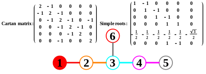
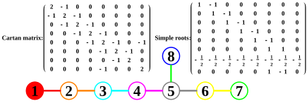
- You may want to take a look at a Powerpoint presentation I just created that demonstrates this math using my Mathematica tools. It shows the generation of all 3D Platonic, Archimedean and Catalan solids, as well as the popular 4D polychora using these concepts. That starts on slide 29. The first 8 slides introduce the material and my interactive demonstration. Slides 9-28 review the Coxeter-Dynkin group theory with Hasse diagrams, etc. View in presentation mode for interactive slide builds. [[3]]
- Jgmoxness (talk) 16:50, 17 February 2023 (UTC)
- You're right :-) Dc.samizdat (talk) 01:19, 17 February 2023 (UTC)
Hasse diagram of E8[edit]
Illustrating the root system of E8 as a poset using Coxeter height is pretty cool. I don't suppose you'd be interested in enriching that illustration a bit? It would be nice to show (relative to the chosen Chevalley basis for the Cartan subalgebra) the nested E7, E6, D5, A4 (8-5-6-7) corresponding to successive node deletions from the Dynkin diagram starting at node 1, as well as the A6, A5, A4 sequence ending in the complementary A4 (4-3-2-1). (I think that trying to show the A7 as well results in too much of a tangle, but perhaps one can highlight the D6.) There might also be some merit in annotating the 56-dimensional Brown structurable algebras and 27-dimensional Albert algebras that one discards as one reduces the algebra, though I don't think the Hasse diagram by itself is a great illustration of those; but they show up nicely on an appropriate projection of the root system onto two axes of which one is the Coxeter height, which is effectively a geometry-enriched Hasse diagram. You probably know more about visualizing these things than I do, but maybe it's useful to have a second pair of eyes? Michael K. Edwards (talk) 01:23, 4 October 2023 (UTC)
ArbCom 2023 Elections voter message[edit]
Hello! Voting in the 2023 Arbitration Committee elections is now open until 23:59 (UTC) on Monday, 11 December 2023. All eligible users are allowed to vote. Users with alternate accounts may only vote once.
The Arbitration Committee is the panel of editors responsible for conducting the Wikipedia arbitration process. It has the authority to impose binding solutions to disputes between editors, primarily for serious conduct disputes the community has been unable to resolve. This includes the authority to impose site bans, topic bans, editing restrictions, and other measures needed to maintain our editing environment. The arbitration policy describes the Committee's roles and responsibilities in greater detail.
If you wish to participate in the 2023 election, please review the candidates and submit your choices on the voting page. If you no longer wish to receive these messages, you may add {{NoACEMM}} to your user talk page. MediaWiki message delivery (talk) 00:34, 28 November 2023 (UTC)