
User:Mcapdevila/Electrolitic

An electrolytic capacitor is a polarized capacitor which anode electrode is made of a special metal on which by anodically oxidation (forming) an insulating oxide layer originates, which acts as the dielectric of the electrolytic capacitor. A non-solid or solid electrolyte which covers the surface of the oxide layer serves as second electrode (cathode) of the capacitor.
Depending on the used nature of the anode metal the family of electrolytic capacitors are divided into three family members:
- Aluminum electrolytic capacitors,
- Tantalum electrolytic capacitors and
- Niobium electrolytic capacitors
Electrolytic capacitors store the electric energy statically by charge separation in an electric field in the dielectric oxide layer between two electrodes like other conventional capacitors. The non-solid or solid electrolyte is the cathode and thus forms the second electrode of the capacitor. This and the storage principle distinguishes them from electrochemical supercapacitors, in which the electrolyte is the conductive connection between two electrodes and the storage occur with double-layer capacitance and pseudocapacitance.
Electrolytic capacitors have - based on the volume - a much higher specific electric capacitance compared to ceramic capacitors and film capacitors, but articulately smaller capacitance than supercapacitors.
All electrolytic capacitors are polarized components by the manufacturing principle and may only be operated with DC voltage. Voltages with reverse polarity, voltage or ripple current higher than specified can destroy the dielectric and thus the capacitor. A possible ripple voltage must not cause reversal. The destruction of electrolytic capacitors can have catastrophic consequences (explosion, fire).
Bipolar electrolytic capacitors which may be operated with AC voltage are special constructions with two anodes connected in revers polarity.
The large capacitance of electrolytic capacitors makes them particularly suitable for passing or bypassing low-frequency signals and storing large amounts of energy. They are widely used in power supplies, and interconnecting stages of amplifiers at audio frequencies.
Basic informations[edit]
Basic principle[edit]

Electrolytic capacitors are using a chemical feature of some special metals, earlier called “valve metals”, on which by anodically oxidation an insulating oxide layer serves as dielectric originates. Applying a positive voltage to the anode material in an electrolytic bath an oxide barrier layer with a thickness corresponding to the applied voltage will be formed (formation). This oxide layer acts as dielectric in an electrolytic capacitor. The properties of this aluminum oxide layer are given in the following table:
| Anode- material |
Dielectric | Permittivity ε |
Oxide structure |
Breakdown voltage (V/µm) |
Voltage proof (nm/V) |
|---|---|---|---|---|---|
| Aluminum | Aluminum oxide Al2O3 | 9.6 | amorphous | 710 | 1.4 |
After forming a dielectric oxide on the rough anode structures a counter-electrode has to match the rough insulating oxide surface. This will be done by the electrolyte which acts as cathode electrode of an electrolytic capacitor. There are a lot of different electrolytes in use. Generally the electrolytes will be distinguished into two species, “non-solid” and “solid” electrolytes. Non-solid electrolytes as a liquid medium which have a ion conductivity by moving ions makes them relatively insensible against voltage spikes or current surges. Solid electrolytes have an electron conductivity and this makes solid electrolytic capacitors sensible against voltages spikes or current surges. The anodic generated insulating oxide layer becomes destroyed if the polarity of the applied voltage changes.

Every electrolytic capacitor in principle forms a "plate capacitor" whose capacitance is greater, the larger the electrode area A and the permittivity ε are and the thinner the thickness (d) of the dielectric is.

The capacitance is proportional to the product of the area of one plate multiplied with the permittivity, divided by the thickness of the dielectric.
The dielectric thickness of electrolytic capacitors is very thin in the range of nano-meter per volt. Otherwise the voltage strengths of these oxide layers are quite high. With this very thin dielectric oxide layer combined with a sufficient high dielectric strength the electrolytic capacitors can already achieve a high volumetric capacitance. This is one reason for the high capacitance values of electrolytic capacitors compared to conventional capacitors.
All etched or sintered anodes have a much higher surface compared to a smooth surface of the same area or the same volume. That increases the later capacitance value, depending on the rated voltage, by the factor of up to 200 for aluminum electrolytic capacitors[1][2]. The large surface compared to a smooth one is the second reason for the relatively high capacitance values of electrolytic capacitors compared with other capacitor families.
One special advantage is given for all electrolytic capacitors. Because the forming voltage defines the oxide layer thickness the voltage proof of the later electrolytic capacitor can be produced very simple for the desired rated value, the so-called “CV-Volume”. That makes electrolytic capacitors fit for uses down to 2 V applications in which other capacitor technologies must stay to much higher limits.
Basic construction of non-solid aluminum electrolytic capacitors[edit]
- Basic construction of aluminum electrolytic capacitors with non-solid electrolytes
-
 Opened winding of an e-cap with multiple connected foils
 -
 Closeup cross-section of an aluminum electrolytic capacitor design, showing capacitor anode foil with oxide layer, paper spacer soaked with electrolyte, and cathode foil
 -
 Construction of a typical single-ended aluminum electrolytic capacitor with non-solid electrolyte


Aluminum electrolytic capacitor with non-solid electrolyte always consists out of two aluminum foils separated mechanically by a spacer, mostly paper, which is saturated with liquid or gel-like electrolyte. One of the aluminum foils, the anode, is etched (roughened) to increase the surface and oxidized (formed). The second aluminum foil called "cathode foil" serves to make electrical contact to the electrolyte. A paper spacer separates the foils mechanically from each other to avoid direct metallic contact. Both foils and the spacer become wound. The winding will be impregnated with liquid electrolyte. The electrolyte, which serves as cathode of the capacitor, covers the etched rough structure of the oxide layer on the anode perfectly and makes the increased anode surface effectual. After impregnation the impregnated winding will be mounted into an aluminum case and sealed.
By design, non-solid aluminum electrolytic capacitor for the contacting of the electrolyte has a second aluminum foil, the so-called cathode foil. This structure of an aluminum electrolytic capacitor construction has a characteristic result because the second aluminum foil, cathode foil is also covered with an insulating oxide layer naturally formed by air. Therefore, there the construction of the electrolytic capacitor consists of two single series-connected capacitors with a capacitance CA of the anode and a capacitance CK of the cathode. The total capacitance of the capacitor Ce-cap is thus obtained from the formula of the series connection of two capacitors:

It follows that the total capacitance of the capacitor Ce-cap mainly is determined due to the anode capacitance CA when the cathode capacitance CK is very large compared with the anode capacitance CA. This requirement is given when the cathode capacitance CK is approximately 10 times higher than the anode capacitance CA. This can be easily achieved because the natural oxide layer on cathode surface has a voltage proof of approximately 1.5 V and is therefore very thin.
Comparison of non-solid and solid types[edit]
Although the present article only refers in essence to aluminum electrolytic capacitors with non-solid electrolyte, an overview of the different types of aluminum electrolytic capacitors is given here in order to highlight the differences. Aluminum electrolytic capacitors are divided by the use of either liquid or solid electrolyte systems into two sub-types. Because the different electrolyte systems are constructed with different materials, they include further sub-types.
- Aluminum electrolytic capacitors with non-solid electrolyte,
- with liquid electrolyte based on ethylene glycol and boric acid, so-called "borax" electrolytes, or based on organic solvents, such as DMF, DMA, GBL, or based on high water containing solvents, for so-called "low impedance”, low ESR" or “high ripple current” e-caps
- Aluminum electrolytic capacitors with solid electrolyte,
- with solid manganese dioxide electrolyte, see Solid aluminum capacitor (SAL)
- with solid polymer electrolyte, see polymer aluminum electrolytic capacitor
- with hybrid electrolytes, solid polymer and liquid, see also polymer aluminum electrolytic capacitor
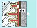
- Principle design differences of the different aluminum electrolytic capacitor sub-types
-
 Al-e-cap with non-solid electrolyte
 -
 Al-e-cap with solid manganese oxide electrolyte, graphite/silver cathode connection
 -
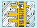 Al-e-cap with polymer electrolyte
 -
 Al-e-cap with polymer electrolyte, graphite/silver cathode connection
 -
 Al-e-cap with polymer and non-solid electrolyte (Hybrid polymer)


Description of the materials:
1: Anode foil, 2: Anode oxide layer (dielectric), 3: Cathode foil, 4: Cathode oxide layer, 5: Non-solid electrolyte, 6: Paper spacer soaked with electrolyte, either non solid or polymer,
7: Conducting polymer, 8: Manganese oxide (MnO2), 9: Graphite, 10: Silver
The following table shows an overview over the main characteristics of the different types of aluminum electrolytic capacitors.
| Electrolyte | Capacitance range (µF) |
Rated- voltage- range (V) |
Typ. ESR 1) 100 kHz, 20 °C (mΩ) |
Typ. ripple current 1) 100 kHz,105 °C (mA) |
Leakage current 1) after 2 minutes at 10 V (µA) |
|---|---|---|---|---|---|
| non-solid Borax or organic |
0.1…2,700,000[3] | 4…630[4] | 800 | 130 | <10 |
| non-solid Water based |
1…18,000 | 4…100 | 360 | 240 | 10 |
| solid Manganese dioxide |
0.1…1,500 | 6.3…40[5] | 400 | 620 | 12 |
| solid Conducting polymer |
2.2…2,700 | 2…125[6] | 25 | 2,500 | 240 |
| solid and non-solid Hybrid electrolyte |
6.8…1000 | 6.3…125[7] | 40 | 1,500 | 100 |
1) Values for a typical capacitor with 100 µF/10…16 V
Aluminum electrolytic capacitors with non-solid electrolyte are the best known and most widely used electrolytic capacitors. In almost all boards of electronic equipment, these components can be found. They are characterized by particularly inexpensive and easy to process base materials.
Al-e-caps with liquid electrolytes based on borax or organic solvents have a large share of standard and professional series in the entire voltage range. Al-e-caps with water-based electrolytes are often found in digital devices for mass production. The e-cap sub-type with solid manganese dioxide electrolyte has served in the past as "tantalum replacement". Polymer aluminum electrolytic capacitors with solid conductive polymer electrolyte are becoming increasingly important, especially in devices with flat design, such as tablet PCs and flat panel displays. Electrolytic capacitors with hybrid electrolytes are relatively new on the market. They combine with their hybrid electrolyte system the improved conductivity of the polymer with the advantage of liquid electrolytes for better self-healing property of the oxide layer, so that the capacitors have both advantages of low ESR and low leakage current.
Materials[edit]
Anode[edit]


Basic material of the anode for aluminum electrolytic capacitors is a foil with a thickness of 20 ~ 100 µm from high purity aluminum with a purity of at least 99.99%.[2][8] This is etched (roughened) in an electrochemical process to increase the effective electrode surface.[9] By etching the surface of the anode, depending on the required rated voltage, the surface can increased by a factor of approximately 200 with respect to a smooth surface.[2]
After etching the aluminum anode the roughed surface will be "anodic oxidized" or "formed". Thereby an electrically insulating oxide layer Al2O3 is formed on the aluminum surface by application of a current in correct polarity if it is inserted in an electrolytic bath. This oxide layer is the capacitor dielectric.
This process of oxide formation is carried out in two reaction steps whereby the oxygen for this reaction has to come from the electrolyte.[10] First, a strongly-exothermic reaction transforms metallic aluminum (Al) into aluminum hydroxide, Al(OH)3:
- 2 Al + 6 H2O → 2 Al(OH)3 + 3 H2 ↑
This reaction is accelerated by a high electric field and by high temperatures, and is accompanied by a pressure buildup in the capacitor housing, caused by the released hydrogen gas. The gel-like aluminum hydroxide Al(OH)3, also called alumina trihydrate (ATH), is converted, via a second reaction step (usually slowly over a few hours at room temperature, more rapidly in a few minutes at higher temperatures), into aluminum oxide, Al2O3:
- 2 Al(OH)3 → 2 AlO(OH) + 2 H2O → Al2O3 + 3 H2O
The aluminum oxide serves as dielectric and also protects the metallic aluminum against aggressive chemical reactions from the electrolyte. However, usually the converted layer of aluminum oxide is not homogeneous. It forms a complex multi-layer structured lamination of amorphous, crystalline and porous crystalline aluminum oxide mostly covered with small residual parts of unconverted aluminum hydroxide. For this reason, in the formation of the anode foil, the oxide film is structured by a special chemical treatment that either an amorphous oxide or a crystalline oxide is formed. The amorphous oxide variety yields higher mechanical and physical stability and lower defects, thus increases the long term stability and lowering the leakage current.

Amorphous oxide has a dielectric ratio of ~1.4 nm/V. Compared to crystalline aluminum oxide which has a dielectric ratio of ~1.0 nm/V the amorphous variety has a 40% lower capacitance at the same anode surface.[11] The disadvantage of crystalline oxide is the greater sensitivity against tensile stress which may lead to micro-cracks when subjected to mechanical (winding) or thermal (soldering) stressors which result in higher post-forming processes.
The various properties of oxide structures have an impact on the subsequent characteristics of the electrolytic capacitors. Anode foils with amorphous oxide are primarily used for electrolytic capacitors with stable long-life characteristics, for capacitors with low leakage current values, and for e-caps with rated voltages up to about 100 volts. Capacitors with higher voltages, for example photoflash capacitors, usually containing anode foils with crystalline oxide.[12],
Because the thickness of the effective dielectric is proportional to the forming voltage the dielectric thickness could be tailored for the rated voltage of the capacitor. F. e. for low voltage types an 10 V electrolytic capacitor has a dielectric thickness of only about 0.014 µm, a 100 V electrolytic capacitor of only about 0.14 µm. Thus, the dielectric strength also influences the size of the capacitor. However, due to standardized safety margins the actual forming voltage of e-caps is higher than the rated voltage of the component.
Aluminum anode foils are manufactured as so-called "mother rolls" of about 500 mm broadness. They are pre-formed for the desired rated voltage and with the desired oxide layer structure. For the production of the capacitors the anode widths and lengths, as required for a capacitor, has to be cut from the mother roll.[13]
Cathode[edit]

The second aluminum foil in the electrolytic capacitor called "cathode foil" serves to make electrical contact to the electrolyte. This foil has a somewhat lower degree of purity of about 99.8%. It is always provided with a very thin oxide layer, which arises from the contact of aluminum surface with the air in a natural way. In order to reduce the contact resistance to the electrolyte and to make it difficult for oxide formation during discharging, the cathode foil is alloyed with metals such as copper, silicon, or titanium. The cathode foil is also etched to enlarge the surface. Their specific capacitance, however, because of the extremely thin oxide layer, which corresponds to a voltage proof of app. 1.5 V, is much higher than that of anode foils.[2] To justify the need for a large surface capacitance of the cathode foil see #Charge/discharge stability.
The cathode foils, same as the anode foils, become manufactured as so called „mother rolls”, from which the widths and lengths are cut off, as required for a capacitor production.
Electrolyte[edit]
His name got the electrolytic capacitor from the electrolyte, the conductive liquid inside the capacitor. As a liquid it can be adapted to the porous structure of the anode and the grown oxide layer with the same shape and form like a "tailor-made" cathode. An electrolyte always consists out of a mixture of solvents and additives to meet the given requirements. The main electrical property of the electrolyte is its conductivity, which physically is an ion-conductivity in liquids. In addition to the good conductivity of operating electrolytes varied demands are made, among other things, chemical stability, high flash point, chemical compatibility with aluminum, low viscosity, low environmental impact and low costs. The electrolyte should also provide oxygen for forming processes and self-healing and that all within a temperature range as large as possible. This diversity of requirements for the liquid electrolyte results in a broad variety of proprietary solutions. [14][15]
Today’s used electrolytic systems can be roughly summarized into three main groups:
- Electrolytes based on ethylene glycol and boric acid. In these so-called glycol or borax electrolyte an unwanted chemical crystal water reaction occurs according to the scheme: "acid + alcohol" gives "ester + water". This borax electrolytes are standard electrolytes used since long times and contain a water content between 5 and 20%. They still working at a maximum temperature of 85 °C or 105 °C in the entire voltage range up to 600 V. Even with these capacitors, the aggressiveness of the water must be prevented by appropriate measures.[16]
- Almost anhydrous electrolytes based on organic solvents, such as Dimethylformamide (DMF), Dimethylacetamide (DMA), or γ-butyrolactone (GBL). These capacitors with organic solvent electrolytes are suitable for temperature ranges from 105 °C, 125 °C or 150 °C, have low leakage current values and have a very good long-term behavior of the capacitors.
- Water based electrolytes with high water contend up to 70% water for so-called “low-impedance”, “low-ESR” or “high-ripple-current” electrolytic capacitors with rated voltages up to 100 V.[17] for low-cost mass-market applications. The aggressiveness of the water for aluminum must be prevented with suitable additives.[18]
Since the amount of liquid electrolyte during operating time of the capacitors decreases over the time through self-healing and by diffusion through the seal the electrical parameters of the capacitors may be adversely affected, the service life or life time of "wet" electrolytic capacitors is limited, see #Life time.
Separator[edit]
Anode and cathode foil must be protected from direct contact with each other, because such contact even at relatively low voltages may lead to a short circuit. In case of direct contact of both foils the oxide layer on the anode surface gives no protection any more. A spacer or separator, made out of a special highly absorbent paper with highly purity, protect the two metal foils against direct contact. This capacitor paper also still serves as a reservoir for the electrolyte to extend the lifetime of the capacitor.
The thickness of the spacer depends on the rated voltage of the electrolytic capacitor. It is up to 100 V between 30 to 75 µm.[19]. For higher voltages, several layers of paper (duplex paper) used to increase the breakdown strength.
Encapsulation[edit]

The encapsulation of aluminum electrolytic capacitors is also made of aluminum in order to avoid galvanic reactions, normally with an aluminum case (can, tub). For radial electrolytic capacitors it is connected across the electrolyte with a non-defined resistance to the cathode (ground). For axial electrolytic capacitors however, the housing is specifically designed with a direct contact to the cathode.
In case of a malfunction, overload or wrong polarity operating inside the electrolytic capacitor housing a substantial gas pressure can arise. The tubs are designed to open a pressure relief vent and release high pressure gas including parts of the electrolyte. It protect against burst, explode or fly away of the metal tub.
For smaller housings the pressure relief vent are carves in the bottom or the notch of the tub. Larger capacitors like screw-terminal capacitors have a lockable overpressure vent and must be mounted in upright position.
Sealing[edit]
The sealing materials of aluminum electrolytic capacitors are different for the different styles. For larger screw-terminal and snap-in capacitors the sealing washer is made of a plastic material. Axial electrolytic capacitors usually have a sealing washer from phenolic resin, which is laminated with a layer of rubber. Radial electrolytic capacitors use a rubber plug with a very dense structure. All sealing materials must be inert to the chemical parts of the electrolyte and may not contain soluble compounds that could lead to contamination of the electrolyte. Otherwise the electrolyte may not be aggressive against the sealing material to avoid leakage.
Production[edit]

The production process start with mother rolls. First the etched, roughened and pre-formed anode foil on the mother roll as well as the spacer paper and the cathode foil will be cut into the required width.[9][8] The foils are fed to an automatic winder, which makes with three sequent steps - terminal welding – winding – length cutting – a wound section in a consecutive operation. In the next production step the wound section fixed at the led out terminals will be soaked with electrolyte under vacuum impregnation. The impregnated winding than will be built into an aluminum case, provided with a rubber sealing disc and mechanically tightly sealed by curling. Thereafter the capacitor is provided with an insulating shrink sleeve film. This optical ready capacitor than will be contacted at rated voltage in a high temperature post-forming equipment for healing all dielectric defects coming from cutting and winding. After post-forming a 100% final measurement of capacitance, leakage current and impedance take place. Taping close the manufacturing process, the capacitors are ready for delivery.
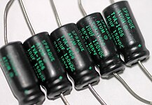
Styles[edit]
- Different styles of non-solid aluminum electrolytic capacitors
-

-

-
-

-


Aluminum electrolytic capacitors with non-solid electrolyte are available in different styles, see pictures above from left to right:
- SMD style (V-chip) for surface mounting on printed circuit boards or substrates
- radial lead terminals (single ended) for vertical mounting on printed circuit boards
- axial lead terminals for horizontal THT mounting on printed circuit boards
- radial pin terminals (snap-in) for power applications
- large style with screw terminals for power applications
Electrical parameters[edit]

The electrical characteristics of capacitors are harmonized by the international generic specification IEC 60384-1. In this standard, the electrical characteristics of capacitors are described by an idealized series-equivalent circuit with electrical components which model all ohmic losses, capacitive and inductive parameters of an electrolytic capacitor:
- C, the capacitance of the capacitor,
- RESR, the equivalent series resistance which summarizes all ohmic losses of the capacitor, usually abbreviated as “ESR”.
- LESL, the equivalent series inductance which is the effective self-inductance of the capacitor, usually abbreviated as “ESL”.
- Rleakage, the resistance that represents the leakage current
Capacitance standard values and tolerances[edit]

The basic unit of electrolytic capacitors capacitance is microfarad (μF, or less correctly uF).
The capacitance value specified in the data sheets of the manufacturers is called rated capacitance CR or nominal capacitance CN and is the value for which the capacitor has been designed. Standardized measuring conditions for e-caps are an AC measuring with 0.5 V at a frequency of 100/120 Hz and a temperature of 20 °C.
The capacitance value of an electrolytic capacitor depends on measuring frequency and temperature. The value at measuring frequency of 1 kHz is about 10% less than the 100/120 :Hz value. Therefore the capacitance values of electrolytic capacitors are not direct comparable and differ from those of film capacitors or ceramic capacitors , whose capacitance is measured at 1 kHz or higher.
Measured with an AC measuring method with 100/120 Hz the measured capacitance value is the closest value to the electrical charge stored in the e-caps. The stored charge is measured with a special discharge method and is called DC capacitance. The DC capacitance is about 10% higher than the 100/120 Hz AC capacitance. The DC capacitance is of interest for discharge applications like photoflash.
The percentage of allowed deviation of the measured capacitance from the rated value is called capacitance tolerance. Electrolytic capacitors are available in different tolerance series, whose values are specified in the E series specified in IEC 60063. For abbreviated marking in tight spaces, a letter code for each tolerance is specified in IEC 60062.
- rated capacitance, series E3, tolerance ±20%, letter code "M“
- rated capacitance, series E6, tolerance ±20%, letter code "M“
- rated capacitance, series E12, tolerance ±10%, letter code "K“
The required capacitance tolerance is determined by the particular application. Electrolytic capacitors, which are often used for filtering and bypassing capacitors don’t have the need for narrow tolerances because they are not used for accurate frequency applications like oscillators.
Rated and category voltage[edit]

In IEC 60384-1 the allowed operating voltage is called "rated voltage" UR or "nominal voltage" UN. The rated voltage is the maximum DC voltage or peak pulse voltage that may be applied continuously at any temperature within the rated temperature range.
The voltage proof of electrolytic capacitors, which is direct proportional to the dielectric layer thickness[1], decreases with increasing temperature. For some applications it is important to use a higher temperature range. Lowering the voltage applied at a higher temperature maintains safety margins. For some capacitor types therefore the IEC standard specify a second "temperature derated voltage" for a higher temperature range, the "category voltage" UC. The category voltage is the maximum DC voltage, peak pulse voltage or superimposed AC voltage that may be applied continuously to a capacitor at any temperature within the category temperature range.
Surge voltage[edit]
Aluminum electrolytic capacitors can be applied for a short time to an overvoltage called surge voltage. The surge voltage indicates the maximum voltage value within the temperature range that may be applied during the life at a frequency of 1000 cycles (each with a dwell time of 30 seconds and a pause of 5 minutes and 30 seconds) without causing any visible damage to the capacitor or a capacitance change of more than 15%.
For capacitors with a rated voltage of ≤ 315 volts the surge voltage is 1.15 times of the rated voltage, and for capacitors with a rated voltage exceeding 315 volts the surge voltage is 1.10 times of the rated voltage.
Transient Voltage[edit]
Aluminum electrolytic capacitors with non-solid electrolyte are relatively insensitive to high and short-term transient voltages higher than surge voltage, if the frequency and the energy content of the transients is low. This ability depends on rated voltage and component size. Low energy transient voltages lead to a voltage limitation similar like a zener diode.
The electrochemical oxide forming processes take place when voltage in correct polarity is applied and generates an additional formation of oxide when transients arise. This formation is accompanied with heat and hydrogen gas generation. This is tolerable, if the energy content of the transient is low. However, when a transient peak voltage causes an electric field strength, which is too high for the dielectric, it can directly cause a short circuit. An unambiguously and general specification of tolerable transients or peak voltages is not possible. In every case, transients arises, the application has to be approved very carefully.
Electrolytic capacitors with solid manganese oxide or polymer electrolyte, aluminum as well as tantalum electrolytic capacitors can not withstand transients or peak voltages higher than surge voltage. Transients for this type of e-caps may destroy the components.
Reverse voltage[edit]

Electrolytic capacitors are polarized capacitors and generally require an anode electrode voltage to be positive relative to the cathode voltage. However, the cathode foil of aluminum electrolytic capacitors is provided with a very thin, natural air-originated oxide layer. This oxide layer has a voltage proof of approximately 1 to 1.5 V.[20] Therefore aluminum electrolytic capacitors with non-solid electrolyte can withstand a very small reverse voltage and f. e. can be measured with an AC voltage of about 0.5 V as specified in relevant standards.
At a revers voltage lower than -1.5 V at room temperature first the cathode aluminum foil begin to build up a oxide layer corresponding to the applied voltage. This is aligned with generating hydrogen gas with increasing pressure. At the same time the oxide layer on the anode foil begins dissolution of the oxide which weaknesses the voltage proof. It’s now a question of the outside circuit whether the increasing gas pressure from oxidization lead to burst of the case or weakened anode-oxide lead to a breakdown with a short circuit. If the outside circuit is high-ohmic the capacitor fails with opening the vent due to high gas pressure. If the outside circuit is low-ohmic an internal short circuit is more probable. In every case a revers voltage lower than -1.5 V at room temperature may catastrophically fail of the component due to dielectric breakdown or overpressure cause the capacitor to burst, often in a spectacularly dramatic fashion. Modern electrolytic capacitors have a safety vent which is typically either a scored section of the case or a specially designed end seal to vent the hot gas/liquid, but ruptures can still be dramatic.
To minimize the likelihood of a polarized electrolytic being incorrectly inserted into a circuit, polarity has to be very clearly indicated on the case, see #Polarity marking.
Special bipolar capacitors designed for AC operation are available, usually referred to as “bipolar”, "non-polarized" or "NP" types. In these, the capacitors have two anode foils of opposite polarity connected in series. On each of the alternate halves of the AC cycle, one anode acts as a blocking dielectric, preventing reverse voltage from damaging the opposite anode.But these bipolar electrolytic capacitors are not adaptable for main AC applications instead of power capacitors with metallized polymer film or paper dielectric.
Impedance[edit]

In general, a capacitor is seen as a storage component for electric energy. But this is only one capacitor function. A capacitor can also act as an AC resistor. Especially aluminum electrolytic capacitors in many applications are used as a decoupling capacitors to filter or bypass undesired biased AC frequencies to the ground or for capacitive coupling of audio AC signals. Than the dielectric is used only for blocking DC. For such applications the AC resistance, the impedance is as important as the capacitance value.
The impedance is the vector sum of reactance and resistance, describes the phase difference and the ratio of amplitudes between sinusoidally varying voltage and sinusoidally varying current at a given frequency in an AC circuit. In this sense impedance can be used like Ohms law

With other words, the impedance is a frequency dependent AC resistance and possesses both magnitude and phase at a particular frequency.

In capacitor data sheets, only the impedance magnitude |Z| is specified, and simply written as "Z". In this sense the impedance is a measure of the capacitor's ability to pass alternating currents.
The impedance can be calculated using the idealized components out of a capacitor's series-equivalent circuit, including an ideal capacitor , a resistor , and an inductance . In this case the impedance at the angular frequency therefore is given by the geometric (complex) addition of ESR, by a capacitive reactance (Capacitance)


and by an inductive reactance (Inductance)
- .

Then is given by

- .

In the special case of resonance, in which the both reactive resistances and have the same value (), then the impedance will only be determined by .


The impedance specified in the datasheets of the various capacitors often show typical curves for the different capacitance values. The impedance at the resonant frequency defines the best working point for coupling or decoupling circuits.
As higher the capacitance as lower is the operable frequency range. Aluminum electrolytic capacitors due to their large capacitance values do have relatively good decoupling properties in the lower frequency range up to about 1 MHz or a little bit more. This and the relatively low price is the reason for using so often electrolytic capacitors in 50/60 Hz standard or switched-mode power supplies.
ESR and dissipation factor tan δ[edit]
- Typical impedance and ESR curves as a function of frequency and temperature
-
 Typical impedance and ESR as a function of frequency
 -
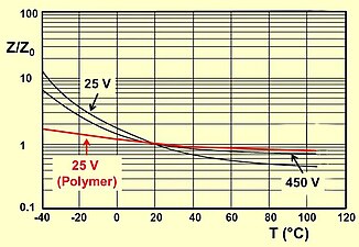 Typical impedance as a function of temperature


The equivalent series resistance (ESR) summarizes all resistive losses of the capacitor. These are the terminal resistances, the contact resistance of the electrode contact, the line resistance of the electrodes, the electrolyte resistance, and the dielectric losses in the dielectric oxide layer.[21]
ESR depends on temperature and frequency. For aluminum electrolytic capacitors with non-solid electrolyte the ESR generally decreases with increasing frequency and temperature[22]. ESR influences the remaining superimposed AC ripple behind smoothing and may influence the circuit functionality. Related to the capacitor ESR is accountable for internal heat generation if a ripple current flow over the capacitor. This internal heat reduces capacitors #lifetime.
Referring to the IEC/EN 60384-1 standard, the impedance values of electrolytic capacitors are measured at 10 kHz or 100 kHz depending on the capacitance and voltage of the capacitor.
For aluminum electrolytic capacitors, out of historical reasons sometimes the dissipation factor tan δ will be specified in the relevant data sheets, instead of the . The dissipation factor is determined by the tangent of the phase angle between the capacitive reactance minus the inductive reactance and the . If the inductance is small, the dissipation factor for a given frequency can be approximated as:

Ripple current[edit]

A ripple current is the RMS value of a superimposed AC current of any frequency and any waveform of the current curve for continuous operation. It arises f. e. in power supplies (including switched-mode power supplies after rectifying an AC voltage and flows as biased charge and discharge current through the decoupling or smoothing capacitor.
Due to the ESR of the capacitor the ripple current IR causes electrical power losses PV el

which result in a heat generation inside the capacitor winding core.
This internal generated heat, together with ambient temperature and possibly other external heat sources leads to a capacitor core temperature which hottest area is located in the winding having a temperature difference of Δ T against the ambient. This heat has to be distributed as thermal losses PV th over the capacitors surface A and the thermal resistance β to the ambient.

The thermal resistance β depends on the case size of the relevant capacitor and if applicableon on additional cooling conditions.

If the internal generated power losses PV el dissipated by thermal radiation, convection, and thermal conduction to the ambient corresponds to the thermal losses PV th, than a temperature balance between capacitor temperature and ambient temperature is given.[23]
Typically, the specified rated value for maximum ripple current in the data sheets of the manufacturers are calculated for a heating the capacitor core (cell) of 10 °C for 85 °C series, 5 °C for 105 °C series and 3 °C for 125 °C series.
The rated ripple current of aluminum electrolytic capacitors with non-solid electrolyte corresponds with the specified life time of the capacitor series. This current may flow permanent over the capacitor up to the maximum temperature during the specified or calculated time. Lower ripple current than specified or forced cooling[23] lengthen the capacitors life time, see #Life time.
The life time of electrolytic capacitors with non-solid electrolyte depends on the evaporations rate and therefore on the core temperature of the capacitor. With force cooling actions or special positioning the capacitor on the PCB the life time could be influenced positively[23].
The ripple current is specified as an effective (RMS) value at 100 or 120 Hz or at 10 kHz at upper category temperature. Non-sinusoidal ripple currents have to be analyzed and separated into their single sinusoidal frequencies by means of Fourier analysis and summarized by squared addition the single currents[24].

Periodical appearing high current pulses, which may be much higher than the rated ripple current have to be analyzed in the same matter.
Because ESR of e-caps decreases with increasing frequencies the ripple current data sheet value, specified at 100/120 Hz, can be higher at higher frequencies. In cases like this manufacturers specify correction factors for ripple current values at higher frequencies. For example, usually the ripple current at 10 kHz can be appr. 30 to 40% higher than the 100/120 value.
If ripple current is exceeded the rated value the corresponding heat generation exceed capacitors temperature limit and may destroy the internal structure (voltage proof, boiling point) of the capacitors. Than the components tends to shorts, opening the vent or explosion. Higher ripple currents than rated are possible only with forced cooling.[25][23]
Charge/discharge stability[edit]

Aluminum electrolytic capacitors with non-solid electrolytes always contain in addition to the anode foil, a cathode foil, which serves as electrical contact to the electrolyte. This cathode foil is provided with a very thin, natural air-originated oxide layer, which act also as a dielectric. Thus, the e-cap construction forms a series circuit of two capacitors, the capacitance of the anode foil CA and the cathode foil CK. As described under #Basic construction the capacitance of the capacitor Ce-cap mainly is determined by the anode capacitance CA when the cathode capacitance CK is approximately 10 times higher than the anode capacitance CA.
Aluminum electrolytic capacitors with non-solid electrolytes normally can be charged up to the rated voltage without any current limitation. This property is a result of the limited ion movability in the liquid electrolyte, which slow down the voltage ramp across the dielectric, and the capacitors ESR.
During discharging the internal construction of the capacitor will reverses the internal polarity. The cathode (-) gets an anode (+), and changes the current flow direction. Over these electrodes two voltages arises. In principle the voltage distribution over the both electrodes behaves as the reciprocally CV product of each electrode.
The design rule of high cathode capacitance causes, than the appearing voltage over the cathode during discharge will not higher than roughly 1.5 V, that is ot's natural air-originated voltage proof. No further post-forming of the cathode foil takes place, which may lead to capacitance degradation.[19][26] Than the capacitors are discharge-proof.
Current surge, peak or pulse current[edit]
Smaller (diameter <25 mm) aluminum electrolytic capacitors with non-solid electrolytes normally can be charged up to the rated voltage without any current surge, peak or pulse limitation up to a peak current value of about 50 A. This property is a result of the limited ion movability in the liquid electrolyte, which slow down the voltage ramp across the dielectric, and the capacitors ESR. Only the frequency of peaks integrated over the time must not exceed the maximal specified ripple current.
Leakage current[edit]


A characteristic property of electrolytic capacitors is defined as “leakage current”. This DC current is represented by the resistor Rleak in parallel with the capacitor in the series-equivalent circuit of electrolytic capacitors, and flows if a voltage is applied.
The leakage current includes all weak imperfections of the dielectric caused by unwanted chemical processes and mechanical damages and is the DC current that can pass through the dielectric after applying a voltage in correct polarity. It depends on the capacitance value, on applied voltage and temperature of the capacitor, on measuring time, on kind of electrolyte, and on preconditions like previous storage time without voltage applied or thermic stress from soldering. (All non-solid e-caps needs a recovery time of some hours after soldering before leakage current measuring. Non-solid e-cap chip capacitors need a recovery time after reflow soldering of about 24 hours.) Leakage current lowers by applying operational voltage by self-healing processes.
Measuring the leakage current it drops in the first minutes after applying DC voltage. In this time the dielectric oxide layer can repair all weaknesses by building up new layers in a self-healing process. The time leakage current drops depends generally on kind of electrolyte. Solid electrolytes leakage current drop very much faster than for non-solid types but remain at a little bit higher level. Wet e-caps with high water contend electrolytes in the first minutes generally have higher leakage current than those with organic electrolyte but after several minutes they reach the same level. Although the leakage current of electrolytic capacitors is higher, compared with the current flow over the insulation resistance at ceramic or film capacitors, the self-discharge of modern non solid electrolytic capacitors can take several weeks.
Leakage current Ileak specification in the data sheets of manufacturers refers to capacitors capacitance value CR, rated voltage UR, a correlation factor and a minimum current value. For example

After a measuring time of 2 or 5 minutes, depending on the data sheet specification, the measured leakage current value has to be lower than the calculated value. Normally the leakage current is always lower the longer the capacitor voltage is applied. The leakage current during operation after f. e. 1 hour is the operational leakage current. This value depends strongly on manufacturers series characteristics. It could be lower than 1/100 of the specified value.
The leakage current depends on the applied voltage and the ambient temperature. The value during continual operation at 85 °C is appr. 4 times higher than at 20 °C. Otherwise the value is appr. ½ reducing the applied voltage on 70% of rated voltage[27].
Non-solid aluminum electrolytic capacitors, which leakage current after an operation time of f. e. one hour remains on a level higher than specified, mostly are internal mechanically damaged by high mechanical stress during mounting.
Dielectric absorption (soakage)[edit]
Dielectric absorption occurs when a capacitor that has remained charged for a long time discharges only incompletely when briefly discharged. Although an ideal capacitor would reach zero volts after discharge, real capacitors develop a small voltage from time-delayed dipole discharging, a phenomenon that is also called dielectric relaxation, "soakage" or "battery action".
| Type of capacitor | Dielectric Absorption |
|---|---|
| Tantalum electrolytic capacitors with solid electrolyte | 2 to 3%,[28] 10%[29] |
| Aluminium electrolytic capacitor with non solid electrolyte | 10 to 15% |
Dielectric absorption may be a problem in circuits, were very small currents are used for in the function of an electronic circuit such as long-time-constant integrators or sample-and-hold circuits. [30] In most applications of electrolytic capacitors supporting power supply lines dielectric absorption is not a problem.
But especially for electrolytic capacitors with high rated voltage the voltage at the terminals generated by the dielectric absorption can be a safety risk to personnel or circuits. In order to prevent shocks most very large capacitors are shipped with shorting wires that need to be removed before they are used.[31]
References[edit]
- ^ a b A. Albertsen, Jianghai Europe, Keep your distance – Voltage Proof of Electrolytic Capacitors, PDF
- ^ a b c d KDK, Specifications for Etched Foil for Anode, Low Voltage [1]
- ^ Cite error: The named reference
DCMCwas invoked but never defined (see the help page). - ^ Cite error: The named reference
630 Vwas invoked but never defined (see the help page). - ^ Vishay, Data sheet 128 SAL-RPM [2]
- ^ Nichicon, CV series PDF
- ^ NIC, NSPE-H Serie, PDF
- ^ a b Production of Aluminum Electrolytic Capacitors, Panasonic PDF
- ^ a b CapXon, Manufacturing Process [3]
- ^ Nichicon, General Descriptions of Aluminum Electolytic Capacitors, 1-3 Dielectric (Aluminum Oxide Layer) PDF
- ^ J.L. Stevens, A.C. Geiculescu, T.F. Strange, Dielectric Aluminum Oxides: Nano-Structural Features and Composites, Fig 6, Page 68, [4]
- ^ S. Parler, Cornell Dubilier CDE, Heating in Aluminum Electrolytic Strobe and Photoflash Capacitors PDF
- ^ Rubycon, TECHNICAL NOTES FOR ELECTROLYTIC CAPACITOR, 2. MANUFACTURE OF ALUMINUM ELECTROLYTIC CAPACITOR PDF
- ^ NON-AQUEOUS ELECTROLYTES and THEIR CHARACTERISTICS, FaradNet Electrolytic Capacitors, Part III: Chapter 10 [5]
- ^ Elna, Principles, 3. Electrolyte, Table 2: An Example of the Composition of the Electrolyte [6]
- ^ Cite error: The named reference
Alfonsowas invoked but never defined (see the help page). - ^ Cite error: The named reference
Uzawawas invoked but never defined (see the help page). - ^ Cite error: The named reference
Stevenswas invoked but never defined (see the help page). - ^ a b K. H. Thiesbürger: Der Elektrolyt-Kondensator., S. 88–91, 4. Auflage, Roederstein, Landshut 1991<!—without ISBN--> (OCLC 313492506).
- ^ Product Information: Aluminum Electrolytic Capacitors FAQ/Capacitor, Power Supply Units RUBYCON CORPORATION [7]
- ^ A. Berduque, Kemet, Low ESR Aluminium Electrolytic Capacitors for Medium to High Voltage Applications, [8] PDF
- ^ Joelle Arnold, Uprating of Electrolytic Capacitors, DfR Solutions [9]
- ^ a b c d A. Albertsen, Jianghai, Electrolytic Capacitor Lifetime Estimation PDF
- ^ Vishay, Aluminium capacitors, Introduction, Revision: 10-Sep-13 1 Document Number: 28356, Chapter Storage, page 7 [10]
- ^ Cite error: The named reference
Vishaypowerwas invoked but never defined (see the help page). - ^ Rubycon, TECHNICAL NOTES FOR ELECTROLYTIC CAPACITOR, CHARGE AND DISCHARGE APPLICATION OF ELECTROLYTIC CAPACITOR, PDF
- ^ Vishay, Aluminium capacitors, Introduction, Revision: 10-Sep-13 1 Document Number: 28356, Chapter Storage, page 7 [11]
- ^ Kemet, Polymer Tantalum Chip Capacitors
- ^ AVX, ANALYSIS OF SOLID TANTALUM CAPACITOR LEAKAGE CURRENT
- ^ Bob Pease, Understand Capacitor Soakage to Optimize Analog Systems [12]
- ^ * "Modeling Dielectric Absorption in Capacitors", by Ken Kundert