
User:Elcap/Types of capacitor
This article may require copy editing for grammar, style, cohesion, tone, or spelling. |
This article is about the commercial discrete capacitors as customary components for use in electronic equipment. For the physical phenomenon, see Capacitor. For explanation of the unit see Capacitance.

Capacitors are a good example of the fact that even the simplest device can become complicated given 250 years of evolution. (Citation J. Ho, T. R. Jow, St. Boggs, Historical Introduction to Capacitor Technology) [1]
Capacitors, together with resistors and inductors, belong to the group of “passive components” in the range of components for electronic equipment. Although in absolute figures the most often produced capacitors are integrated capacitors, f. e. in DRAMs or in flash memorys structures these article is concentrated on capacitors as discrete components.
Capacitors today are industrial products produced in very large quantities for use in electronic and in electrical equipment. Globally, the market for fixed capacitors was estimated with approximately US$18 billion in 2008 for 1,400 billion (1.4 x 10¹²) pieces.[2] This market in point of quantity is dominated by ceramic capacitors with estimated of approximately 1,000 billion (1 x 10¹²) produced pieces per year [3]
Detailed estimated figures in value for the main capacitor families are:
- Ceramic capacitors with US$8.3 billion (46 %);
- Aluminum electrolytic capacitors with US$ 3.9 billion (22 %);
- Film capacitors and Paper capacitors with US$ 2.6 billion, (15 %);
- Tantalum electrolytic capacitors with US$ 2.2 billion (12 %);
- Super capacitors (Double-layer capacitors) with US$ 0.3 billion (2 %); and
- others like silver mica and vacuum capacitors with US$ 0.7 billion (3 %).
All other capacitor types are negligible in terms of value as well as in quantity compared with the above types.
Capacitors – general remarks[edit]
Theory of conventional capacitor construction[edit]

In a conventional capacitor, the electric energy is stored statically by charge separation, typically electrons, in an electric field between two electrode plates. The amount of charge stored per unit voltage is essentially a function of the size, the distance, and the material properties of the plates and the material, the dielectric, in between the electrodes, while the potential between the plates is limited by the breakdown field strength of the dielectric.
Nearly all conventional industrial produced capacitors without some special styles like “feed-through capacitors” are constructed as “plate capacitors” even if their electrodes and the dielectric between are wound or rolled to a winding. The capacitance formula for plate capacitors is:
- .

That means, that the capacitance C for conventional capacitors increases with area A of the electrodes and with permittivity ε of the dielectric material and decreases with the distance d. The capacitance is therefore greatest in devices made from materials with a high permittivity, large plate area, and small distance between plates.
Theory of electrochemical capacitor construction[edit]
_NT.PNG)
1. IHP Inner Helmholtz Layer
2. OHP Outer Helmholtz Layer
3. Diffuse layer
4. Solvated ions
5. Peculiar adsorptive ions (Pseudocapacitance)
6. Solvent molecule.
Beneath the conventional static storage of electric energy in an electric field two more storage principles to store electric energy in a capacitor exist. They can to be found in so called electrochemical capacitors. Supercapacitors, also known as electrical double-layer capacitors (EDLC) or ultracapacitors do not have, in contrast to ceramic, film and electrolytic capacitors a conventional dielectric. The capacitance value of an electrochemical capacitor is determined by two very special high-capacity storage principles which are only owned by these capacitors. These principles are the :
- electrostatic storage of the electrical energy within Helmholtz double layers achieved on the phase interface between the surface of the electrodes and the electrolyte (double-layer capacitance) and the
- electrochemical storage of the electrical energy achieved by a faradaic electron charge-transfer by peculiar adsorpted ions with redox reactions (pseudocapacitance)
Double-layer capacitance and pseudocapacitance add up to a common inextricably capacitance value of a supercapacitor.
Frequent used capacitors and their names[edit]
Capacitors are divided into two mechanical groups: Fixed capacitors with fixed capacitance values and variable capacitors with variable (trimmer) or adjustable (tunable) capacitance values.
Most important group is the group of the fixed capacitors. They have developed historically, as well as the variable capacitors, but got special names. A lot of them got their names from the material used as dielectric. But for a systematical classification of the different types these characteristics can’t be used, because already one of the oldest capacitor type, the electrolytic capacitor, is not named by it’s dielectric material but by their cathode construction. So the mostly used capacitor type names are historical grown without any relation to a common systematic to physics or materials used as dielectric.
The frequent used capacitors and their names are:
- Ceramic capacitors and
- Film capacitors and paper capacitors have been named and can be characterized on the basis of the material used as a dielectric of the component.
- Aluminum, tantalum and niobium electrolytic capacitors were named after the material used as the anode and the construction of the cathode (electrolyte)
- Supercapacitors is the generic name for the family of electrochemical capacitors comprising of
- Double-layer capacitors have been named from the physical phenomenon of the Helmholtz double layer with storing the electrical energy statically in a double-layer capacitance
- Pseudocapacitors got their name from their capability to store electric energy electro-chemically with a redox reaction in a pseudocapacitance
- Hybrid capacitors are the combination of double-layer and pseudo capacitors deliver super high power density
- Silver mica, glass, silicon, air-gap and vacuum capacitors are named and also can be specified to the dielectric used but are seldom used nowadays.
Each of these capacitor types or also called families, that are a group of components having similar physical design features, contains a lot of different variants of capacitors, which may include several styles mostly differ in the form of the terminals. The picture below shows the different types or families out of the fixed capacitors for use in electronic equipment.

In addition to the above shown capacitor types or families, which derived their name from historical development rather than functional application, there are many individual capacitors that have been named based on their application. Some of them are:
- Power capacitors, motor capacitors, DC-link capacitors, suppression capacitors, audio crossover capacitors, lighting ballast capacitors, snubber capacitors, coupling, decoupling or bypassing capacitors, etc.
Each of these capacitors can be constructed out of more than one of the capacitor families, f. e. suppression capacitors can be made as a ceramic or as a film capacitors
Beneath these discrete capacitors some special and not so often used versions exists. That are f. e. build-in capacitors with metal conductive areas in different layers of a multi-layer printed circuit board. Last but not least capacitors can be made by twisting together 2 pieces of insulated wire, makes a Gimmick capacitor.
Types of dielectric[edit]

During the time from beginning the first experiments with the leyden jar capacitors a lot of different materials, chemical and physical specialties has been developed. Most used dielectrics now are
- Ceramics
- Plastic films
- Oxide layer on metal (Aluminum, Tantalum, Niobium)
- Natural materials like mica,glass, paper, air, vacuum
All of them store their electrical charge statically within an electric field between two (parallel) electrodes. Beneath this conventional capacitors a relatively new capacitor was developed in the last four centuries:
- Electrochemical capacitors, also called Supercapacitors, Double-layer capacitors, Pseudocapacitors, or Ultracapacitors.
Supercapacitors don't have a conventional dielectric. They store their electrical charge statically in Helmholtz double-layers and additional electrochemical with a faradayic charge transfer with redox reactions called pseudocapacitance, see picture on the right hand side.
The most important material parameters of the different dielectrics used and the appr. Helmholtz-layer thickness are given in the table below.
| Capacitor style | Dielectric | Permittivity at 1 kHz |
Maximim/realized. dielectric strength V/µm |
Minimum thickness of the dielectric µm |
|---|---|---|---|---|
| Ceramic capacitors, Class 1 |
paraelectric | 12…40 | < 100(?) | 1 |
| Ceramic capacitors, Class 2 |
ferroelectric | 200…14000 | < 25(?) | 0.5 |
| Film capacitors | Polypropylene ( PP) | 2.2 | 650/450 | 2.4...3.0 |
| Film capacitors | Polyethylen terephthalate, Polyester (PET) |
3.3 | 580/280 | 0.7...0.9 |
| Film capacitors | Polyphenylene sulfide (PPS) | 3.0 | 470/220 | 1.2 |
| Film capacitors | Polyethylene naphthalate (PEN) | 3.0 | 500/300 | 0.9...1.4 |
| Film capacitors | Polytetrafluoroethylene (PTFE) | 2.0 | 450(?)/250 | 5.5 |
| Paper capacitors | Paper | 3.5…5.5 | 60 | 5…10 |
| Aluminium electrolytic capacitors | Aluminium oxide Al2O3 |
9,6[9] | 710 | < 0.01 (6.3 V) < 0.8 (450 V) |
| Tantalum electrolytic capacitors | Tantalum pentoxide Ta2O5 |
26 [9] | 625 | < 0.01 (6.3 V) < 0.08 (40 V) |
| Niobium electrolytic capacitors | Niobium pentoxide, Nb2O5 |
42 | 455 | < 0.01 (6.3 V) < 0.10 (40 V) |
| Supercapacitors Double-layer capacitors |
Helmholtz double-layer | - | - | < 0.001 (2.7 V) |
| Vacuum capacitors | Vacuum | 1 | 40 | - |
| Air gap capacitors | Air | 1 | 3.3 | - |
| Glass capacitors | Glas | 5…10 | 450 | - |
| Mica capacitors | Mica | 5…8 | 118 | 4...50 |
The plate area of capacitor is a part of the construction and can be adapted to the wanted capacitance value. Therefore the permittivity and the dielectric thickness are the physical determining parameter for capacitors. Apart from these basic parameters that can vary significantly in real capacitors, the processability of the materials is crucial. Thin, mechanically flexible sheets can be wrapped or stacked easily processing to large designs with high capacitance values. Razor-thin metallized sintered ceramic layers covered with metallized electrodes however, offer the best conditions for the miniaturization of circuits with SMD styles.
A short view to the figures in the table above gives the explanation for some simple facts:
- Supercapacitors followed by
- Electrolytic capacitors have the highest capacitance density because the extreme thin dielectric thickness.
- Ceramic capacitors class 2 do have much higher capacitance values in a given case than class 1 capacitors because of their much higher permittivity.
- Film capacitors with their different plastic film material do have a small spread in the dimensions for a given capacitance/voltage value of a film capacitor because the minimum dielectric film thickness differs between the different film materials.
Capacitance and voltage range[edit]

The different types of capacitors are available commercially, with capacitance ranging from the picofarad, microfarad range to more than hundreds of farad, and voltage ratings up to hundred kilovolts. In general, the higher the capacitance and voltage rating, the larger the physical size of the capacitor, and the higher the cost.
Miniaturization[edit]

Miniaturization is the magic word in electronics. For semiconductor components, miniaturization was witnessed by an empirical observation called Moore's Law that predicted that the number of transistors on an integrated circuit for minimum component cost doubles every 18 months.[10][11]
Also for capacitors the miniaturizing of the components in the last four decades has took place. As in other parts of electronics, volumetric efficiency measures the performance of electronic function per unit volume. For capacitors, the volumetric efficiency is measured with the "CV product", calculated by multiplying the capacitance (C) by the maximum voltage rating (V), divided by the volume. In the time period from 1970 to 2005, capacitor volumetric efficiencies have improved dramatically. Some types of capacitors have improved much faster than others, allowing their use in new applications and in markets previously dominated by other designs.
- One of the first breakthrough in miniaturizing of capacitors was the “winding” of the electrodes beginning in the 1930th
-
 Stacked paper capacitor (Block capacitor) from 1923 for noise decoupling (blocking) in telegraphy lines
 -
 Wound metallized paper capacitor from beginning 1930th in hardpaper case, capacitance value specified in “cm” out of the cgs system. 5000 cm corresponds to 28 nF
 -
 Folded wet aluminum electrolytic capacitor, Bell System 1929, view onto the folded anode which was mounted in a squared housing (not shown) filled with liquid electrolyte
 -
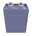
 Two 8 μF, 525 V wound wet aluminum electrolytic capacitors in paper housing sealed with tar out of a 1930's radio.


Overlapping range of applications[edit]
These individual capacitors can perform their application independent of their affiliation to an above shown capacitor type, so that an overlapping range of applications between the different capacitor types exists.

Capacitors – types and styles[edit]
Ceramic capacitors[edit]

A ceramic capacitor is a non-polarized fixed capacitor out of two or more alternating layers of ceramic and metal in which the ceramic material acts as the dielectric and the metal acts as the electrodes. The ceramic material is composed out of a mixture of finely ground granules paraelectric or ferroelectric materials, modified by a lot of accurate mixed oxides, which are necessary to achieve the capacitor’s desired characteristics. The electrical behavior of the ceramic material is divided into two stability classes:
- Class 1 ceramic capacitors with high stability and low losses for temperature compensating in resonant circuit application, common EIA/IEC code abbreviations: C0G/NP0, P2G/N150, R2G/N220, U2J/N750 etc.
- Class 2 ceramic capacitors with high volumetric efficiency for buffer, by-pass and coupling applications, common EIA/IEC code abbreviations: X7R/2XI, Z5U/E26, Y5V/2F4, X7S/2C1, etc.
The great plasticity of ceramic raw material delivers ideal solutions for many special applications and is the reason for the enormous diversity of styles, shapes and great dimension spread of ceramic capacitors. The smallest discrete capacitor, for instance, is a “01005” chip capacitor with the dimension of only 0.4 mm x 0.2 mm.
The construction of ceramic multilayer capacitors with mostly a lot of alternating layers results in a lot of single capacitors connected together in parallel. This connection of single capacitors in parallel increases the capacitance value but decreases all losses and parasitic inductances. Therefore ceramic capacitors are dedicated for high frequencies and higher current pulse loads.
Because the thickness of the ceramic layer, the dielectric, easily can be chosen and produced by the desired application voltage, ceramic capacitors are available with rated voltages up to some 10 kV range.
- Ceramic capacitors for special applications
Moreover, some ceramic capacitors of special shapes and styles are used as capacitors for special application like
- RFI/EMI suppression capacitors for connection to the supply mains, also known as safety capacitors [12] [13]
- X2Y® capacitors for bypassing and decoupling applications [14]
- Feed-through capacitors for noise suppression by low-pass filters [15]
- Ceramic power capacitors for transmitters and HF applications. [16] [17]
- The great plasticity of ceramic raw material delivers ideal solutions for many special applications and is the reason for the enormous diversity of styles within the family of ceramic capacitors
-
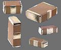
 Multi-layer ceramic capacitors (MLCC chips) for SMD mounting
 -
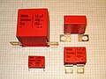
 Ceramic X2Y® decoupling capacitors
 -
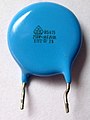 Ceramic EMI suppression capacitors for connection to the supply mains (safety capacitor)
 -
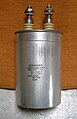
 High voltage ceramic power capacitor


Film capacitors[edit]

Film capacitors or plastic film capacitors are non polarized capacitors with an insulating plastic film as the dielectric. The dielectric films are drawn in a special process to an extremely thin thickness, provided with metallic electrodes and wound into a cylindrical shaped winding. The electrodes of film capacitors may be metallized aluminum or zinc applied one- or both sided directly to the surface of the plastic film, resulting in
- Metallized film capacitors
or a separate metallic foil overlying the film, than called
- Film/foil capacitors.
Metallized film capacitors owns self-healing properties, dielectric breakdowns or shorts between the electrodes are not leading to the destruction of the component. The metallized type of construction makes it possible to produce winded capacitors with larger capacitance values (up to 100 µF and larger) in smaller cases than within the film/foil construction.
Film/foil capacitors or metal foil capacitors are made of two plastic films as the dielectric each covered with a thin metal foil, mostly aluminium, as the electrodes. The advantage of this construction is the easy contactability of the metal foil electrodes and the excellent current pulse strength.
A key advantage of every film capacitor internal construction is direct contact to the electrodes on both ends of the winding. This contact keeps all current paths to the entire electrode very short. The setup behaves like a large number of individual capacitors connected in parallel, thus reducing the internal ohmic losses (ESR) and the parasitic inductance (ESL). The inherent geometry of film capacitor structure results in very low ohmic losses and a very low parasitic inductance, which makes them especially suitable for applications with very high surge currents (snubbers) and for AC power applications, or for applications at higher frequencies.
The plastic films used as dielectric for film capacitors are Polypropylene (PP), Polyester (PET), Polyphenylene sulfide (PPS), Polyethylene naphthalate (PEN), and Polytetrafluoroethylene or Teflon (PTFE). Polypropylene film material with a market share of something about 50 % and Polyester film with something about 40 % are the most used film materials. The rest of something about 10 % will be used by all other materials including PPS and paper with roughly 3 %, each. [18] [19]
| Film material, abbreviated codes | |||||
|---|---|---|---|---|---|
| Film characteristics | PET | PEN | PPS | PP | |
| Relative permittivity at 1 kHz | 3.3 | 3.0 | 3.0 | 2.2 | |
| Minimum film thickness (µm) | 0.7…0.9 | 0.9…1.4 | 1.2 | 2.4…3.0 | |
| Moisture absorption (%) | low | 0.4 | 0.05 | <0.1 | |
| Dielectric strength (V/µm) | 580 | 500 | 470 | 650 | |
| Commercial realized voltage proof (V/µm) |
280 | 300 | 220 | 400 | |
| DC voltage range (V) | 50—1000 | 16—250 | 16—100 | 40—2000 | |
| Capacitance range | 100 pF—22 µF | 100 pF—1 µF | 100 pF—0.47 µF | 100 pF—10 µF | |
| Application temperature range (°C) | -55 — +125 /+150 | -55 — +150 | -55 — +150 | -55 — +105 | |
| ΔC/C versus temperature range (%) | ±5 | ±5 | ±1.5 | ±2.5 | |
| Dissipation factor (•10−4) | |||||
| at 1 kHz | 50—200 | 42—80 | 2—15 | 0.5—5 | |
| at 10 kHz | 110—150 | 54—150 | 2.5—25 | 2—8 | |
| at 100 kHz | 170—300 | 120—300 | 12—60 | 2—25 | |
| at 1 MHz | 200—350 | – | 18—70 | 4—40 | |
| Time constant RInsul•C (s) | at 25 °C | ≥10000 | ≥10000 | ≥10000 | ≥100000 |
| at 85 °C | 1.000 | 1.000 | 1.000 | 10.000 | |
| Dielectric absorption ( %) | 0.2—0.5 | 1—1.2 | 0.05—0.1 | 0.01—0.1 | |
| Specific capacitance (nF•V/mm3) | 400 | 250 | 140 | 50 | |
- Film capacitors for special applications
Some film capacitors of special shapes and styles are used as capacitors for special application like
- High pulse current load is the most important feature of film capacitors so many of the available styles do have special terminations for high currents
-
 Radial style (single ended) for through-hole solder mounting on printed circuit boards
 -
 SMD style for printed circuit board surface mounting, with metallized contacts on two opposite edges
 -
 Radial style with heavy-duty solder terminals for snubber applications and high surge pulse loads
 -
 Heavy-duty snubber capacitor with screw terminals


Film power capacitors[edit]

A related component type to above film capacitors is the power film capacitor. Although the materials and construction techniques used for large power film capacitors mostly are very similar to those used for ordinary film capacitors, capacitors with high to very high power ratings for applications in power systems and electrical installations are often classified separately, for historical reasons. The standardization of ordinary film capacitors is oriented on electrical and mechanical parameters as components for use in electronic equipment. The standardization of power capacitors contrary to that is strongly focused on rules for the safety of personnel and equipment, given by the local regulating authority.
As modern electronic equipment gained the capacity to handle power levels that were previously the exclusive domain of "electrical power" components, the distinction between the "electronic" and "electrical" power ratings has become less distinct. In the past, the boundary between these two families was approximately at a reactive power of 200 volt-amps, but modern power electronics can handle increasing amounts of power.
Film power capacitors mostly use polypropylene film as dielectric, but up to now metallized paper capacitors (MP capacitors) and mixed dielectric film capacitors with polypropylen as dielectric and metallized paper for cost sensitive types or as field-free carrier electrodes (soggy foil capacitors) for high AC or high current pulse loads are in use. These winding of these capacitors can be filled with an insolating oil or with epoxy resin to reduce air bubbles inside the winding, which can be force short circuits.
Film power capacitors can be found wherever there is a need for converters to change voltage, current or frequency of electric power to protect semiconductor components, to store or deliver abruptly electric energy or to improve the power factor. The rated voltage range of these capacitors is from approximately120 V AC (capacitive lighting ballasts) to 100 kV. [23]
- Power film capacitors for applications in power systems, electrical installations and plants
-
 Power film capacitor for AC power factor correction (PFC), packaged in a cylindrical metal can
 -
 Power film capacitor in rectangular housing
 -
-
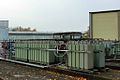
 75MVAR substation capacitor bank at 150kV


Electrolytic capacitors[edit]
- Schematic representation of the structure electrolytic capacitors class=
-
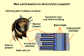 Schematic representation of the structure of a wound aluminum electrolytic capacitor with non solid (liquid) electrolyte
 -
 Schematic representation of the structure of a sintered tantalum electrolytic capacitor with solid electrolyte


- Electrolytic capacitors have a metallic anode which is covered with an oxidized layer used as dielectric. The second electrode of electrolytic capacitors is a non solid or solid electrolyte. Electrolytic capacitors are polarized electrical components. Three families of electrolytic capacitors are available:
- Aluminum electrolytic capacitors with aluminum oxide as dielectric
- Tantalum electrolytic capacitors with tantalum pentoxide as dielectric
- Niobium electrolytic capacitors with niobium pentoxide as dielectric.
The anode of electrolytic capacitors is highly roughned to extend the surface area which increases the capacitance value. This and the relatively high permittivity of the oxide layers gives this capacitors the very high capacitance per unit volume compared with film- or ceramic capacitors.
Because the permittivity of the tantalum pentoxide is approximately three times higher than aluminium dioxide tantalum electrolytic capacitors are significant smaller for a same capacitance/voltage value than aluminum electrolytic capacitors. But the permittivity of the oxide layers only determine the dimensions of electrolytic capacitors. The electrical parameters of the capacitors are established by the material and composition of the electrolyte, especially by the conductivity. Here three general types of electrolytes are used:
- non solid (wet, liquid) electrolyte, electrical conductivity approximately 10 mS/cm, cheapest version
- solid manganese oxide electrolyte, electrical conductivity approximately 100 mS/cm, for high quality and long time stable capacitors
- solid conductive polymer electrolyte (Polypyrrole), electrical conductivity approximately 10,000 mS/cm[24], for capacitors with very low ESR values down to values <10 mΩ.
That means, the internal losses of aluminum, tantalum and niobium electrolytic capacitors, prevailing used for decoupling and buffering applications, are determined by the electrolyte used.
| Anode material | Electrolyte | Capacitance range (µF) |
Max. rated voltage at 85 °C (V) |
Upper categorie temperature (°C) |
Specific ripple current (mA/mm3) 1) |
|---|---|---|---|---|---|
| Aluminum (roughned foil) |
non solid, f. e. Ethylene glycol, DMF, DMA, GBL |
0.1…2,700,000 | 550 | 150 | 0,05…2,0 |
| solid, Manganese dioxide (MnO2 |
0,1…1500 | 40 | 175 | 0,5…2,5 | |
| solid conductive polymere (f. e. Polypyrrole) |
10…1500 | 25 | 125 | 10…30 | |
| Tantalum (roughned foil) |
non solid Sulfuric acid |
0,1…1000 | 630 | 125 | – |
| Tantalum (sintered) |
non solid sulfuric acid |
0,1–15.000 | 150 | 200 | – |
| solid Manganese dioxide (MnO2 |
0,1…3300 | 125 | 150 | 1,5…15 | |
| solid conductive polymere (f. e. Polypyrrole) |
10…1500 | 35 | 125 | 10…30 | |
| Niobium (sintered) |
solid Manganese dioxide (MnO2 |
1…1500 | 10 | 125 | 5…20 |
| solid conductive polymere (f. e. Polypyrrole) |
2,2…1000 | 25 | 105 | 10…30 | |
| |||||
The internal losses of aluminum, tantalum and niobium electrolytic capacitors, prevailing used for decoupling and buffering applications, are determined by the electrolyte used.
The larger capacitance per unit volume of electrolytic capacitors than other types, making them valuable in relatively high-current and low-frequency electrical circuits, e.g. in power supplies filters for decoupling unwanted AC components from DC power connections or as coupling capacitors in audio amplifiers, for passing or bypassing low-frequency signals and storing large amounts of energy. The relatively high capacitance value of an electrolytic capacitor combined with the very low ESR of the polymer electrolyte of polymer capacitors, especially in SMD styles, makes this capacitors to an often used power supply capacitor in laptops and table PC’s and is here in competition to MLC chip capacitors.
Bipolar electrolytics (also called Non-Polarized capacitors) contain two anodized aluminium foils, behaving like two capacitors connected in series opposition.
- Electolytic capacitors for special applications:
- Aluminum, tantalum and niobium electrolytic capacitors, prevailing used for decoupling and buffering applications, are available in a broad spread of types and dimensions
-
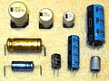 Axial, radial (single ended) anv V-chip styles of aluminum electrolytic capacitors
 -
 Snap-in style of aluminum electrolytic capacitors for power applications
 -
 SMD style for surface mounting of aluminum electrolytic capacitors with polymer electrolyte
 -
 Tantalum electrolytic chip capacitors for surface mounting


Supercapacitors[edit]


Supercapacitors, also known as electrical double-layer capacitors (EDLC) or ultracapacitors, are electrochemical capacitors. The term "supercapacitor" has been established in the literature as generic term for all electrochemical capacitors [28] because a "double-layer capacitance" only is a part of a supercapacitor.
Supercapacitors do not have a conventional dielectric. The capacitance value of an electrochemical capacitor is determined by two very special high-capacity storage principles which are only owned by these capacitors. These principles are the :
- electrostatic storage of the electrical energy within Helmholtz double layers achieved on the phase interface between the surface of the electrodes and the electrolyte coin a (double-layer capacitance) and the
- electrochemical storage of the electrical energy achieved by a faradaic electron charge-transfer by peculiar adsorpted ions with redox reactions coin a (pseudocapacitance)
Double-layer capacitance and pseudocapacitance add up to a common inseparable capacitance value of a supercapacitor. However, they can be effective with very different parts of the total capacitance value depending on the design of the electrodes. A pseudocapacitance may be higher by a factor of 100 as a double-layer capacitance with the same surface of the electrode. [29] Unlike batteries the faradaic electron charge-transfer of the pseudocapacitance in a supercapacitor the ions simply cling to the atomic structure of an electrode. This energy storing with with fast redox reactions makes charging and discharging of supercapacitors much faster than batteries.
Supercapacitors are divided, due to the design of its electrodes in three different capacitor families:
- Double-layer capacitors are those electrochemical capacitors in which the static double-layer capacitance predominates significantly and the percentage of faradaic pseudocapacitance is very low.
- Pseudocapacitors are electrochemical capacitors with predominant faradaic pseudocapacitance and the percentage of static double-layer capacitance is very low.
- Hybrid capacitors do have special electrodes which wears both a double-layer as well as a pseudocapacitance. These capacitors include some new developments with special electrodes, f. e. the lithium-ion capacitors.
Supercapacitors have the highest capacitance values per unit volume and do have the greatest energy density of all capacitors. Supercapacitors are manufactured with capacitance values up to 12,000 F/1.2 V. Therefore Its specific capacitance is up to 10000 times larger than this of the electrolytic capacitors. However, this this high capacitance will in comparison with batteries only about 10 % of the capacity of batteries.
While existing supercapacitors have energy densities that are approximately 1/10 that of a conventional battery, their power density is generally 10 to 100 times as great. Power density combines the energy density with the speed at which the energy can be delivered to the load. Supercapacitors tolerate large numbers of rapid charge and discharge cycles.
This makes them most suited for smaller battery replacement. In parallel connection with batteries they can realize a large cycle strength, high reliability and longer lifetime of the circuit. The broad spread of applications for supercapacitors range from providing longtime small currents for data storage of static memory (SRAM) in electronic equipment up to the area of power electronics with very high currents as in the KERS system in the Formula 1 cars for short time electrical energy storage/delivery or in the recovery of braking energy (recuperation) in vehicles such as buses and trains.
In these electrochemical capacitors, the electrolyte is the conductive connection between the two electrodes. This distinguishes them from electrolytic capacitors, in which the electrolyte is the cathode, and thus forms the second electrode.
Super capacitors are polarized components, which may only be operated with the correct polarity. The polarity is determined for capacitors with asymmetric electrode on design reasons, for capacitors with symmetrical electrodes the polarity is created by a voltage applied during production.
All supercapacitors have very specific electrical parameters. They mostly are not interchangeable at all, especially the types for higher energy densities. But supercapacitors with their different electrical behavior may be used for a lot of different applications from long time, low current demand to very high short time peak current demand. Out of reason of the different requirements coming from the different applications the IEC standard for “Fixed electric double layer capacitors for use in electronic equipment” IEC 62391-1 specify four application classes:
- Class 1 mainly used for RAM memory backup with discharge current units ranging from nA to μA,
- Class 2 for energy storage, mainly used for driving motors require a short time operation, with discharge current units ranging from mA to A,
- Class 3 for energy storage with higher power demand for a long time operation, with discharge current units ranging from mA to A,
- Class 4 for energy storage for applications that requires instantaneous power with relatively large current even with a short operating time.
Very special for supercapacitors are the multitudinous different used trade names. Following terms manufacturers uses:
- APowerCap, BestCap, BoostCap, CAP-XX, DLCAP, EVerCAP, DynaCap, Faradcap, GreenCap, Goldcap, HY-CAP, Kapton capacitor, Super capacitor, SuperCap, PAS Capacitor, PowerStor, PseudoCap, Ultracapacitor.
- Double-layer, Lithium-Ion and supercapacitors
-
 Double-layer capacitor with 1 F at 5.5 V for data buffering
 -
 Radial (single ended) style of lithium ion capacitors for high energy density
 -
Supercapacitor/Ultracapacitor cells and modules for high current loads


Miscellaneous Capacitors for special applications[edit]
Beneath the above described capacitors covering more or less nearly the total market of discrete capacitors some new developments or very special capacitor types as well as older types can be found in electronics.
New developments
- Integrated capacitors,: in integrated circuits, small capacitors can be formed through appropriate patterns of metallization on an isolating substrate. These capacitors formed as multiple capacitor arrays without any other semiconductive parts can be manufactured as customized capacitor arrays in discrete packaging. [30]
- Glass capacitors, first Leyden jar capacitor was a glass capacitor, today (2012) used as SMD version for ultra-reliable and ultra-stable applications
Special power capacitors
- vacuum capacitors, used in high power RF transmitters
- SF6 gas filled capacitors, used as capacitance standard in measuring bridge circuits
Older capacitor types
- Mica capacitors, were the first capacitors with stable frequency behavior and low losses for military RF applications during World War II
- Air-gap capacitors, first spark-gap transmitters used air-gap capacitors,
Special constructed capacitors
- Printed circuit board capacitors, metal conductive areas in different layers of a multi-layer printed circuit board can act as a highly stable capacitor. It is common industry practice to fill unused areas of one PCB layer with the ground conductor and another layer with the power conductor, forming a large distributed capacitor between the layers.
- Gimmick, these capacitors are made by twisting together 2 pieces of insulated wire. Values usually range from 3 pF to 15 pF. Usually used in homemade VHF circuits for oscillation feedback.
- Miscellaneous capacitors
-
 Some 1nF x 500VDC rated silver mica capacitors
 -
 Vacuum capacitor with uranium glass encapsulation


Variable capacitors[edit]
Variable capacitors may have their capacitance changed by mechanical motion. Generally two versions of variable capacitors has to be to distinguished
- Tuning capacitor – variable capacitor for intentionally and repeatedly tuning an oscillator circuit in a radio or another tuned circuit
- Trimmer capacitor – small variable capacitor usually for one-time oscillator circuit internal adjustment
Variable capacitors include capacitors that use a mechanical construction to change the distance between the plates, or the amount of plate surface area which overlaps. They mostly use air as dielectric medium.
Semiconductive variable capacitance diodes are not capacitors in the sense of passive components but can change their capacitance as a function of the applied reverse bias voltage and are used like a variable capacitor. They have replaced much of the tuning and trimmer capacitors.
- Variable capacitors
-
 Air gap tuning capacitor
 -
 Vacuum tuning capacitor
 -
 Trimmer capacitor for through hole mounting
 -
 Trimmer capacitor for surface mounting


Capacitor features comparisons[edit]
| Capacitor type | Dielectric used | Features/applications | Disadvantages |
|---|---|---|---|
| Ceramic capacitors | |||
| Ceramic Capacitors Class 1 |
paraelectric ceramic mixture of Titanium dioxide modified by additives | Predictable linear and low capacitance change with operating temperature. Excellent high frequency characteristics with low losses. For temperature compensating in resonant circuit application. Available in voltages up to 15,000 V | Low permittivity ceramic, capacitors with low volumetric efficiency, larger dimensions than Class 2 capacitors |
| Ceramic Capacitors Class 2 |
ferroelectric ceramic mixture of barium titanate and suitable additives | High permittivity ceramic, capacitors with high volumetric efficiency, smaller dimensions than Class 1 capacitors. For buffer, by-pass and coupling applications. Available in voltages up to 50,000 V. | Lower capacitance stability and higher losses than Class 1 capacitors. Capacitance changes with change in applied voltage, with frequency and with aging effects. Class 2 capacitors are slightly microphonic |
| Film capacitors | |||
| Metallized film capacitors | PP, PET, PEN, PPS, (PTFE) | Metallized film capacitors are significantly smaller in size than film/foil versions and have self-healing properties to improve reliability | Thin metallized electrodes limit the maximum current carrying capability respectively the maximum possible pulse voltage. |
| Film/foil film capacitors | PP, PET, PTFE | Film/foil film capacitors do have the highest surge ratings, pulse voltage respectively peak current capability are higher than for metallized types. | Film/foil film capacitors have no self-healing properties, internal short may destroy the capacitor. Larger dimensions than metallized versions |
| Polypropylene (PP) film capacitors |
Polypropylene (Treofan®) |
Has become the most popular film capacitor dielectric. Predictable linear and low capacitance change with operating temperature, suitable for applications in Class-1 frequency-determining circuits and precision analog applications. They are available for these precision applications in very narrow capacitances. Extremely low dissipation factor. Low moisture absorption, therefore also suitable for "naked" designs without any coating. High insulation resistance. Usable in high power applications such as snubber or IGBT applications. Used also in AC power applications, such as motor run capacitors or PFC capacitors. Due to very low dielectric losses high frequency and high power applications like induction heating are possible. Polypropylene film capacitors are widely used for safety capacitors/EMI suppression, including connection to the power supply mains. | Maximum operating temperature of 105 °C. The relatively low permittivity of 2.2 is a slight disadvantage, and PP film capacitors tend to be somewhat larger than other film caps. More susceptible to damage from transient over-voltages or voltage reversals than oil-impregnated MKV-capacitors forpulsed power energy discharge applications. |
| Polyester (PET) film capacitor) (Mylar capacitor) |
Polyethylene terephthalate, Polyester (Hostaphan®, Mylar®) | Smaller in size when compared with polypropylene film capacitors of comparable specifications. Low moisture absorption. PET film capacitors have almost completely replaced metallized paper capacitors and polystyrene film capacitors for most DC electronic applications. Polyester film capacitors are mainly used for general purpose applications or semi-critical circuits with operating temperatures up to 125 °C. Operating voltages up to 60,000 V DC. | Usable at low (AC power) frequencies. Limited use in power electronics due to its tendency to have higher losses with increasing temperature and frequency. |
| Polyethylene naphthalate (PEN) film capacitors |
Polyethylene naphthalate (Kaladex®) | PEN has better stability at high temperatures than PET. Therefore, PEN film capacitors are more suitable for high temperature applications and for SMD packaging. PEN capacitors are mainly used for non-critical filtering, coupling and decoupling in electronic circuits, when the temperature dependencies do not matter. | Because of the smaller relative permittivity and lower dielectric strength of the PEN polymer, the dimensions of PEN film capacitors are larger for a given capacitance and rated voltage value than for PET film capacitor. |
| Polyphenylene Sulfide (PPS) film Capacitors |
Polyphenylene (Torelina®) | PPS film capacitors do have a small temperature dependence over the entire temperature range and a narrow frequency dependence of the capacitance in a wide frequency range. The dissipation factor of PPS film capacitors is quite small and over a wide range very stable. PPS film capacitors can withstand temperatures up to 270 °C without damaging the film quality, so that PPS film capacitors are suitable for surface mount devices (SMD), and can tolerate the increased reflow soldering temperatures for lead-free soldering mandated by the RoHS 2002/95/EC directive | Above 100 °C, the dissipation factor surpasses increases so it could run hotter in some AC applications, but can operate without degradation at higher temperatures. Cost is usually higher compared to Polypropelene |
| Polytetrafluoroethylene (PTFE) film capacitors, (Teflon film capacitors) |
Polytetrafluoroethylene (Teflon®) | Lowest loss solid dielectric. Operating temperatures up to 250 °C, extremely high insulation resistance, and good stability. Used in stringent, mission-critical applications | Large size (due to low dielectric constant), and higher cost than other film capacitors. |
| Polycarbonate (PC) film capacitor |
Polycarbonate | Polycarbonate film capacitors have almost completely replaced by polypropylene (PP) film capacitors | Limited manufacturers |
| Polystyrene (PS) film capacitors |
Polystyrene (Styroflex) | Styroflex film capacitors have almost completely replaced by polyester (PET) film capacitors. | Limited manufacturers |
| Polysulphone film capacitors |
Polysulfone | Similar to polycarbonate. Can withstand full voltage at comparatively higher temperatures. | Only development, no series found (2012) |
| Polyamide film capacitors |
Polyamide | Operating temperatures of up to 200 °C. High insulation resistance, good stability and low dissipation factor. | Only development, no series found (2012) |
| Polyimide film capacitors (Kapton capacitors) |
Polyimide (Kapton) | Polyimides have the highest dielectric strength of any known plastic film dielectric. | Only development, film could not drawn thin enough, no series found (2012) |
| Film power capacitors | |||
| Metallized paper power capacitors | Paper impregnated with insulating oil or epoxy resin | Impregnated metallized paper with self-healing properties was extensively used for older capacitors, using wax, oil, or epoxy as an impregnant. Oil-Kraft paper capacitors are still used in certain high voltage applications. Has mostly been replaced by polypropylene film capacitors. | Large size. Also, paper is highly hygroscopic, absorbing moisture from the atmosphere despite plastic enclosures and impregnates. Absorbed moisture degrades performance by increasing dielectric losses and decreasing insulation resistance. |
| Paper film/foil power capacitors | Kraft paper impregnated with oil | Paper covered with metal foils as electrodes was used for older capacitors or cheapest design. Designed specifically for intermittent duty, high current discharge applications. | Physically large and heavy. Significantly lower energy density than polypropylene dielectric. Not self-healing. Device may fail catastrophically due to high stored energy. |
| Polypropylene dielectric, field-free paper power capacitors (MKV power capacitors) | Double-sided (field-free) metallized paper as carrier of the electrodes, polypropylene dielectric, impregnated with insulating oil, epoxy resin or insulating gas | Self-healing properties, very low losses, high insulation resistance, high inrush current strength and high thermal stability. for heavy duty applications like commutating with high reactive power, high frequencies and a high peak current load and in general AC applications. | Physically larger than polypropylene power capacitors. |
| Single or double sided metallized polypropylene power capacitor | Polypropylen, impregnated with insulating oil, epoxy resin or insulating gas | PP power capacitors have the highest capacitance per volume of all power capacitors and self-healing propeties. They are used over a broad range of applications like General-purpose AC capacitors motor capacitors, Smoothing or filtering capacitors, DC link capacitors, Snubber or clamping capacitors, Damping AC capacitors, DC capacitors for series resonant circuits, DC discharge capacitors, AC commutation capacitors, AC capacitors for power factor correction. | critical for reliable high voltage operation and very high inrush current loads, limited heat resistance (105 °C) |
| Polypropylene film/foil power capacitors | Polypropylen, impregnated with insulating oil, epoxy resin or insulating gas | PP film/foil power capacitors have the highest high inrush current strength | Larger than the PP metallized versions, no self-healing properties |
| Electrolytic capacitors | |||
| Electrolytic capacitors with non solid (wet, liquid) electrolyte |
Aluminum dioxide Al2O3 |
Wet aluminum electrolytic capacitors have very large capacitance to volume ratio, high capacitance values up to 2,700,000 µF/6.3 V, high voltage ratings up to 550 V, and lowest cost per cap/volt values. Primary applications where low losses and high stability of capacitance are not of major importance, especially for lower frequencies, like by-pass and coupling applications as well as smoothing and buffer applications in power supplies and DC-links. | Polarized capacitor. Leakage current is not negligible, Relatively high ESR and ESL values limits high ripple current and high frequency applications. Lifetime calculation required because drying out phenomenon. May vent or burst when overloaded , overheated or connected wrong polarized. Water based electrolyte may vent open after reaching end-of-life-point, showing ”capacitor plague”-like pictures. |
| Tantalum pentoxide Ta2O5 |
Wet tantalum electrolytic capacitors (wet slug) [31] have the lowest leakage current of all electrolytic capacitors. High voltage ratings up to 630 V (tantalum film) resp. 125 V (tantalum sinter body). Hermetic sealed very stable and reliable capacitors. For military, space and similar applications | Polarized capacitor. Explodes quite violently when voltage rating, ripple current rating, or slew rates are exceeded, or when subjected to reverse voltage. Very high prices. | |
| Electrolytic capacitors with solid manganese dioxide electrolyte |
Aluminum dioxide Al2O3 Tantalum pentoxide Ta2O5, Niobium pentoxide Nb2O5 |
Due to the 3-times higher permittivity of tantalum and niobium pentoxide this capacitors do have smaller dimensions for a given cap/volt value compared with aluminum electrolytic capacitors. Manganese dioxide electrolyte gives stable electrical parameters, for good long-term performance at high temperature, ESR lower than non solid electrolytic capacitors. Electrolytic capacitors with manganese electrolyte will be replaced more and more by electrolytic capacitors with polymer electrolyte. | Polarized capacitor. Voltage limited to about 125 V. Low voltage ratings and limited transient, reverse or surge voltage tolerance, could combust upon failure. ESR much higher than electrolytic capacitors with conductive polymer electrolytes |
| Electrolytic capacitors with solid polymer electrolyte (Polymer capacitors) |
Aluminum dioxide Al2O3, Tantalum pentoxide Ta2O5, Niobium pentoxide Nb2O5 |
A distinctive difference in the electrical parameters of electrolytic capacitors lies in electrolyte. The use of a solid polymer electrolyte instead of a liquid electrolyte in electrolytic capacitors, results in improvements of greatly reduced ESR, higher ripple current ratings, extended operational life and stable electrical parameters. Polymer capacitors have selfhealing properties[32]. Primary applications are as smoothing and buffer capacitors in smaller power supplies especially in SMD versions. | Polarized capacitor. Leakage current is the highest of all electrolytic capacitors. Higher prices than non solid or solid manganese dioxide electrolytic capacitors. Voltage limited to about 100 V. Explodes quite violently when voltage rating, current rating, or slew rates are exceeded, or when subjected to reverse voltage. |
| Supercapacitors | |||
| Supercapacitors Electrochemical capacitors Double-layer capacitors Pseudocapacitors |
Helmholtz double-layer plus faradaic pseudo-capacitance | A relatively new capacitor technology. Their energy density is typically tens to hundreds of times greater than conventional electrolytic capacitors, therefore the application area of EDLC’s are more or less comparable with batteries, not with common capacitors. Extremely large capacitance to volume ratio, small size, relatively low ESR. Available up to thousands of farads. Smaller ones used for RAM memory backup. Larger components and stacks of components often used to temporarily provide power to equipment during battery replacement. Can rapidly absorb and deliver much larger currents than batteries during charging and discharging, and they can be cycled hundreds of thousands of times making them valuable for hybrid vehicles. |
Polarized, low operating voltage per capacitor cell. Groups of cells are stacked to provide higher overall operating voltage. Relatively high cost. |
| Hybrid capacitors Lithium ion capacitors (LIC) |
Helmholtz double-layer plus faradaic pseudo-capacitance, Anode doped with lithium ions | The lithium ion capacitors belong to the hybrid capacitors out of the family of supercapacitors. They have a higher operating voltage and therefore a higher energy density compared with common EDLC’s but smaller to lithium ion batteries (LIB). LIC’s are safer in use than LIB’s in which thermal runaway reactions may occur. | Polarized, low operating voltage per capacitor cell. Groups of cells are stacked to provide higher overall operating voltage. Relatively high cost. |
| Miscellanous capacitors | |||
| Air gap capacitors | Air | Air-gap capacitors have a low dielectric loss, can be used for resonating HF circuits for high power HF welding. | physically large, and relatively low capacitance. |
| Vacuum capacitors | Vacuum | Extremely low losses. Used for high voltage high power RF applications, such as transmitters and induction heating where even a small amount of dielectric loss would cause excessive heating. Can be self-healing if arc-over current is limited. | Very high cost, fragile, physically large, and relatively low capacitance. |
| SF6 gas filled capacitors | SF6 gas | High precision capacitors [33], extremely low losses, very high stability, up to 1600 kV rated voltage, used as capacitance standard in measuring bridge circuits | Very high cost |
| Metallized mica capacitors (Silver mica capacitors) | Mica | Very high stability, no aging, low losses, used for HF and low VHF RF circuits, and as capacitance standard in measuring bridge circuits. Mostly replaced by Class 1 ceramic capacitors | Higher cost
than class 1 ceramic capacitors |
| Glass capacitors | Glass | Stability and frequency characteristics are better than silver mica capacitors. Ultra-reliable, ultra-stable, and resistant to nuclear radiation. Capable of operation over -75 °C to +200 °C with short overexposure to +250 °C[34] | Higher cost than class 1 ceramic capacitors |
| Integrated capacitors | oxide-nitride-oxide (ONO) | New development. Thin capacitors (down to 100 µm). Smaller footprint than most MLCC, low ESL, Very high stability up to 200 °C. High reliability (silicon standards) | Customized production |
| Variable capacitors | |||
| Air gap tuning capacitors | Air | Circular or different logarithmic cut of the rotor electrode for different curves of capacitance, split cut of the rotor or the stator electrode for symmetric adjustment, ball bearing axis for noise reduced adjustment. For high professional devices. | large dimensions, high costs |
| Vacuum tuning capacitors | Vacuum | Extremely low losses. Used for high voltage high power RF applications, such as transmitters and induction heating where even a small amount of dielectric loss would cause excessive heating. Can be self-healing if arc-over current is limited. | Very high cost, fragile, large dimensions |
| SF6 gas filled tuning capacitor | SF6 | Extremely low losses. Used for very high voltage high power RF applications. | Very high cost, fragile, large dimensions |
| Air gap trimmer capacitor | Air | Have been mostly replaced by semiconductive variable capacitance diodes | High cost compared with electronic adjustment |
| Ceramic trimmer capacitor | Class 1 ceramic | Linear and stable frequency behavior over wide temperature range | High cost compared with electronic adjustment |
Electrical characteristics[edit]
Series-equivalent circuit[edit]

Capacitors as discrete components deviate from the ideal capacitor in a number of ways. An ideal capacitor only stores and releases electrical energy, without dissipating any. In reality, all capacitors have losses and parasitic inductive parts. These imperfections within the capacitor's material and construction can have positive properties like the linear frequency and temperature behavior in class 1 ceramic capacitors or negative properties like the non-linear behavior of the voltage dependent characteristic of the capacitance in class 2 ceramic capacitors or the insufficient dielectric insulation of electrolytic capacitors leading to leakage currents.
All properties can be defined and specified by a series equivalent circuit composed out of an idealized capacitance and additional electrical components which model all losses, and inductive parameters of a capacitor. In this series-equivalent circuit the electrical characteristics of a capacitors is defined by
- C, the capacitance of the capacitor,
- Rinsul, the insulation resistance of the dielectric, not to be confused with the insulation of the housing
- Rleak, the resistance representing the leakage current of the capacitor,
- RESR, the equivalent series resistance which summarizes all ohmic losses of the capacitor, usually abbreviated as “ESR”.
- LESL, the equivalent series inductance which is the effective self-inductance of the capacitor, usually abbreviated as “ESL”.
Using a series equivalent circuit instead of a parallel equivalent circuit is harmonized by the international generic specification IEC/EN 60384-1.
Capacitance standard values and tolerances[edit]
The “rated capacitance” CR or “nominal capacitance” CN is the value for which the capacitor has been designed. The actual capacitance of capacitors depends on the measuring frequency and the ambient temperature. Standardized conditions for capacitors are a low-voltage AC measuring method at a temperature of 20 °C with frequencies of
- 100 kHz, 1 MHz (preferred) or 10 MHz for non-electrolytic capacitors with CR ≤ 1 nF:
- 1 kHz or 10 kHz for non-electrolytic capacitors with 1 nF < CR ≤ 10 μF
- 100/120 Hz for electrolytic capacitors
- 50/60 Hz or 100/120 Hz for non-electrolytic capacitors with CR > 10 μF
For supercapacitors a voltage drop method for measuring the capacitance value is applied.
Capacitors are available in different of geometrically increasing preferred values whose values are specified in the E series standards specified in IEC/EN 60063. According to the number of values per decade, these were called the E3, E6, E12, E 24 etc. series. The range of units used to specify capacitor values has expanded to include everything from pico- (pF) over nano- (nF) and mikrofarad (µF) to farad (F). The use of millifarad and kilofarad is uncommon.
The percentage of allowed deviation of the capacitance from the rated value is called capacitance tolerance. The actual capacitance value of a capacitor should be within the tolerance limits, or the capacitor is out of specification. For abbreviated marking in tight spaces, a letter code for each tolerance is specified in IEC/EN 60062.
| E series | Tolerance | |||
|---|---|---|---|---|
| CR > 10 pF | Letter code | CR < 10 pF | Letter code | |
| E 96 | 1 % | F | 0,1 pF | B |
| E 48 | 2 % | G | 0,25 pF | C |
| E 24 | 5 % | J | 0,5 pF | D |
| E 12 | 10 % | K | 1 pF | F |
| E 6 | 20 % | M | 2 pF | G |
| E3 | −20/+50 % | S | - | - |
| −20/+80 % | Z | - | - | |
The required capacitance tolerance is determined by the particular application. The narrow tolerances of E24 to E96 will be used for high-quality circuits like precision oscillators and timers. On the other hand, for general applications such as non-critical filtering or coupling circuits, the tolerance series E12 or E6 are sufficient. Electrolytic capacitors, which are often used for filtering and bypassing, mostly have a tolerance range of ±20% and need to be available only within E6 (or E3) series values.
Temperature dependence of capacitance[edit]
The capacitance of a capacitor varied with the temperature. The different dielectrics of the many capacitor types shows great differences in the temperature dependence of the capacitance. These temperature coefficient is expressed in parts per million (ppm) per degree Celsius for class 1 ceramic capacitors or in % over the total temperature range for all others.
| Type of capacitor, dielectric material |
Temperature coefficient ΔC/C |
Application temperature range |
|---|---|---|
| Ceramic capacitors class 1 paraelectric NP0 |
± 30 ppm/K (±0,5 %) | −55…+125 °C |
| Ceramic capacitors class 2, ferroelectric X7R |
±15 % | −55…+125 °C |
| Ceramic capacitors class 2, ferroelectric Y5V |
+22 % / −82 % | −30…+85 °C |
| Film capacitors Polypropylene ( PP) |
±2,5 % | −55…+85/105 °C |
| Film capacitors Polyethylen terephthalate, Polyester (PET) |
+5 % | −55…+125/150 °C |
| Film capacitors Polyphenylene sulfide (PPS) |
±1,5 % | −55…+150 °C |
| Film capacitors Polyethylene naphthalate (PEN) |
±5 % | −40…+125/150 °C °C |
| Film capacitors Polytetrafluoroethylene (PTFE) |
? | −40…+130 °C |
| Metallized paper (impregnated) | ±10 % | −25…+85 °C |
| Aluminium electrolytic capacitors Al2O3 |
±20 % | −40…+85/105/125 °C |
| Tantalum electrolytic capacitors Ta2O5 |
±20 % | −40…+125 °C |
Frequency dependence of capacitance[edit]
Most of all of the different discrete capacitor types have more or less frequency changes with increasing frequencies. The dielectric strength of class 2 ceramic and plastic film diminishes with rising frequency. Therefore their capacitance value decreases with increasing frequency. This phenomenon for ceramic class 2 and plastic film dielectrics is related to the dielectric relaxation in which the time constant of the electrical dipoles is the reason for the frequency dependence of permittivity. The graphs below show typical frequency behavior of the capacitance for ceramic and film capacitors.
- Frequency dependence of capacitance for ceramic and film capacitors
-
 Frequency dependence of capacitance for ceramic class 2 capacitors (NP0 class 1 for comparisation)
 -
 Frequency dependence of capacitance for film capacitors with different film materials


For electrolytic capacitors, especially for electrolytic capacitors with non-solid electrolyte additional a mechanical moving mechanism of the ions take place. The movability of the ions in the liquid is limited so that at higher frequencies not all areas of the roughned anode structure will be covered with ions carrying the electric charge. As higher the anode structure is roughned as more the capacitance value decreases with increasing frequency. Low voltage types which have high roughned anodes can have capacitance drops down to approximately 10 to 20 % at 100 kHz of the value measured at 100 Hz.
Voltage dependence of capacitance[edit]
Capacitors may also change capacitance with applied voltage. This effect is more prevalent in class 2 ceramic capacitors. The ferroelectric material of class 2 capacitors depends on the applied voltage. As higher the applied voltage as lower the permittivity. The change of capacitance can drop down to values of -80 % of the value measured with the standardized measuring voltage of 0.5 or 1.0 V. This behavior is a small source of non-linearity using class 2 ceramic capacitors in low-distortion filters and other analog applications and in audio applications this can be the reason for harmonic distortions.
Film capacitors and electrolytic capacitors have no significant voltage dependence of capacitance.
- Voltage dependence of capacitance for some different class 2 ceramic capacitors
-
 Simplified diagram of the change in capacitance as a function of the applied voltage for 25-V capacitors in different kind of ceramic grades
 -
 Simplified diagram of the change in capacitance as a function of applied voltage for X7R ceramics with different rated voltages


Rated and category voltage[edit]

The voltage at which the dielectric in a capacitor becomes conductive is called the breakdown voltage, and is given by the product of the dielectric strength and the separation between the electrodes. The dielectric strength on the other hand depends on temperature, frequency, shape of the electrodes e.t.c. so that the breakdown voltage depends on several outside influences. Because a breakdown in a capacitor normally is a short circuit and destroy the component irrevocable the allowed operating voltage for a capacitor out of safety reasons has to be lower than the minimal breakdown voltage. The operating voltage for a real discrete industrial produced capacitor is specified in such manner, that the voltage applied during application may be applied continuously throughout the life of the capacitors.
Regarding to IEC/EN 60384-1 standard the allowed operating voltage is called “rated voltage” or “nominal voltage”. The rated voltage (UR) is the maximum DC voltage or peak value of pulse voltage which may be applied continuously to a capacitor at any temperature within the rated temperature range.
The voltage proof of nearly all capacitors decreases with increasing temperature. For some applications it is important to use a higher temperature range. Lowering the voltage applied at a little bit higher temperature the safety margins will be the same. For some capacitor types therefore the IEC standard specify a second “temperature derated voltage” for a higher temperature range, the “category voltage”. The category voltage (UC) is the maximum DC voltage or peak value of pulse voltage which may be applied continuously to a capacitor at any temperature within the category temperature range.
The relation between both voltages and temperatures is given in the picture right.
Impedance[edit]

In general, a capacitor is seen as a storage component for the electric energy. But this is only one sides view of the function of a capacitor. The other side view is the function of a capacitor as an AC resistor. In very much cases the applied capacitors will be used as decoupling capacitors not only to store the electrical charge but also to filter or bypass undesired biased AC frequencies to the ground. Additional a lot of applications using the capacitors for coupling AC signals; the dielectric only is used for blocking DC. For all this applications the AC resistance is as important as the capacitance value.
The frequency depending AC resistance is called impedance and is the complex ratio of the voltage to the current in an AC circuit. Impedance extends the concept of resistance to AC circuits, and possesses both magnitude and phase at a particular frequency unlike resistance, which has only magnitude.


The magnitude represents the ratio of the voltage difference amplitude to the current amplitude, is the imaginary unit, while the argument gives the phase difference between voltage and current.


In data sheets of capacitors, only the magnitude of the impedance |Z| will be specified, and simply written as “Z” so that the formula for the impedance can be written in Cartesian form

where the real part of impedance is the resistance (for capacitors ) and the imaginary part is the reactance .


As shown in the series-equivalent circuit of a capacitor the real component include an ideal capacitor , an inductance and a resistor . The total reactance of a capacitor at the angular frequency therefore is given by the geometric (complex) addition of a capacitive reactance (Capacitance) and an inductive reactance (Inductance): .


To calculate the impedance now the resistance has to be added geometric and then is given by


The impedance is a measure of the ability of the capacitor to pass alternating currents. In this sense the impedance can be used like Ohms law

to calculate either the peak or the effective value of the current or the voltage.
In the special case of resonance, in which the both reactive resistances
- and
have the same value (), then the impedance will only be determined by .


The impedance specified in the datasheets of the various capacitors often show typical curves for the different capacitance values. With increasing frequency first the impedance decreases down to a minimum. The lower the impedance, the more easily alternating currents can be passed through the capacitor. At the apex, the point of resonance, where XC has the same value than XL, the capacitor has the lowest impedance value. Here only the ESR determines the impedance. With frequencies above the resonance the impedance increases again due to the ESL of the capacitor. The capacitor becomes to an inductance.
As shown in the graph the higher capacitance values can fit the lower frequencies better while the lower capacitance values can fit better the higher frequencies.
Aluminum electrolytic capacitors due to their large capacitance values do have relatively good decoupling properties in the lower frequency range up to about 1 MHz. This is the reason for using electrolytic capacitors in standard or switched-mode power supplies behind the rectifier for smoothing application.
Ceramic and film capacitors are already out of their smaller capacitance values suitable for higher frequencies up to several 100 MHz. They also have due to their construction with end-surface contacting of the electrodes significantly lower parasitic inductance makes them suitable for higher frequency applications. To cover a very wide range of frequencies, often an electrolytic capacitor is connected in parallel with a ceramic or film capacitor.
Many new developments in capacitors are targeted at reducing the parasitic inductance ESL. Thus increase the resonance frequency of the capacitor and, for example, can follow the constantly increase of the switching speed of digital circuits. First step war the miniaturizing especially in the SMD multilayer ceramic chip capacitors (MLCC), which increases the resonance frequency. A further reduction of the parasitic inductance is achieved by contacting the electrodes on the longitudinal side of the chip instead of the lateral side. The "face-down" construction associated with the multi-anode technology also in tantalum electrolytic capacitors has led to a reduction of the ESL. But new developed capacitor families such as the so-called MOS capacitor or silicon capacitors offer solutions when capacitors for very high frequencies up to the GHz range are needed.
Inductance (ESL) and self-resonant frequency[edit]
ESL in industrial capacitors is mainly caused by the leads and internal connections used to connect the plates to the outside world. Large capacitors tend to have higher ESL than small ones because the distances to the plate are longer and every mm counts as an inductance.
For any discrete capacitor, there is a frequency above DC at which it ceases to behave as a pure capacitance. This frequency where is as high as is called the self-resonant frequency. The self-resonant frequency is the lowest frequency at which the impedance passes through a minimum. For any AC application the self-resonant frequency is the highest frequency capacitors can be used as a capacitive component.


This is f. e. critically important with decoupling high-speed logic circuits from the power supply. The decoupling capacitor supplies transient current to the chip. Without decouplers, the IC demands current faster than the connection to the power supply can supply it, as parts of the circuit rapidly switch on and off. To counter this potential problem, circuits frequently use multiple bypass capacitors—a small (100 nF or less) capacitor rated for high frequencies and a large electrolytic rated for lower frequencies and, occasionally, an intermediate value capacitor.
Ohmic losses, ESR, dissipation factor, and quality factor[edit]
The summarized losses in discrete, commercially available capacitors for the electronics are ohmic AC losses. DC losses will be specified as "leakage current" or “insulating resistance” and are negligible for an AC specification. This AC losses are non-linear, it may depend on frequency, temperature, age, and for some special types on humidity. The losses results out of two physical conditions,
- the line losses with the internal supply line resistances, the contact resistance of the electrode contact, the line resistance of the electrodes, and in “wet” aluminum electrolytic capacitors as well as in supercapacitors especially the limited conductivity of liquid electrolytes and
- the dielectric losses out of the dielectric polarzation
The largest share of these losses in larger capacitors is usually the frequency depending ohmic dielectric losses. For smaller ones, especially for wet electrolytic capacitors, the conductivity of liquid electrolytes may exceed the dielectric losses. To measure these losses, the measurement frequency must be clearly defined. However, since commercially available capacitors with capacitance values cover a range from pF (10-12 F) to some 1000 F in supercapacitors with 15 orders of magnitude, it is not possible to capture the entire range with only one frequency. Regarding to IEC 60384-1 standard, the ohmic losses of capacitors should be measured at the same frequency used to measure the capacitance. That are:
- 100 kHz, 1 MHz (preferred) or 10 MHz for non-electrolytic capacitors with CR ≤ 1 nF:
- 1 kHz or 10 kHz for non-electrolytic capacitors with 1 nF < CR ≤ 10 μF
- 100/120 Hz for electrolytic capacitors
- 50/60 Hz or 100/120 Hz for non-electrolytic capacitors with CR > 10 μF
The measuring results of the summarized resistive losses of a capacitor may be specified either as equivalent series resistance (ESR), as dissipation factor(DF, tan δ), or as quality factor (Q), depending on the application requirements for the capacitor types.
Capacitors with higher ripple ripple current loads applied in their application like electrolytic capacitors, will be specified with an ESR. ESR can be shown as ohmic part in the above vector diagram, see paragraph “Impedance”. ESR values are specified in the datasheets per individual types. With an ESR the heat dissipation inside the capacitor body arise if a current flow easily is to calculate individually for each capacitor.


The heat dissipation is a mark for the maximal power (AC load, ripple current, pulse load, e.t.c.) a capacitor can withstand.
The losses of film capacitors and some class 2 ceramic capacitors are mostly specified with the dissipation factor tan δ. These capacitors do have smaller losses than electrolytic capacitors and mostly are used at higher frequencies up to some hundred MHz. However the numeric value of the the dissipation factor, measured at the same measuring frequency, is independently of the individual capacitance value, and can be specified for a capacitor series with a range of capacitance. The dissipation factor is determined as the tangent of the reactance ( - ) and the ESR., and can be shown as the angle δ between imaginary and the impedance axis in the above vector diagram, see paragraph “Impedance”.
If the inductance is small, the dissipation factor can be approximated calculated as:


Capacitors with very low losses, that are ceramic Class 1 and Class 2 capacitors, the resistive losses are specified with a quality factor (Q). Especially ceramic Class 1 capacitors are suitable for LC resonant circuits with very high frequencies up to the GHz range, and high precise high and low pass filters. For an electrically resonant system, the Q factor represents the effect of electrical resistance, and characterizes a resonator's bandwidth relative to its center or resonant frequency . The quality factor is defined as the reciprocal value of the dissipation factor.


A high Q value is for resonant circuits a mark of the quality of the resonance.
| Capacitor type | Capacitance (pF) |
ESR at 100 kHz (mΩ) |
ESR at 1 MHz (mΩ) |
tan δ at 1 MHz (10−4) |
Quality factor |
|---|---|---|---|---|---|
| Silicon capacitor [35] | 560 | 400 | — | 2,5 | 4000 |
| Mica capacitor [36] | 1000 | 650 | 65 | 4 | 2500 |
| Class 1 ceramic capacitor (NP0) [37] |
1000 | 1600 | 160 | 10 | 1000 |
Limiting current loads[edit]
A capacitor is as well a component store electrical energy as an AC resistor couple AC voltage and AC current between two points within the electric circuit. But every effective AC current flow through a capacitor generates heat inside the capacitor body. The heat dissipation (power loss) and is caused by and squared value of the effective (r.m.s.) current


The same power loss can be written with the dissipation factor as


Every effective AC current flow through a capacitor generates heat inside the capacitor body. AC currents may be a
- ripple current, an effective (r.m.s.) AC current, coming from an AC voltage superimposed of an DC bias, a
- pulse current, an AC peak current, coming from an voltage peak, or an
- AC current, an effective (r.m.s.) sinusoidal current
The generated heat causes as well as a warming up of the total capacitor body as heat up contact areas selective at critical points. Ripple currents and AC currents warm up the total body. Pulse currents, especially in metallized film capacitors, are heating up the contact areas between end spray (schoopage) and metallized electrodes. The generated temperature influences in general the breakdown voltage of dielectric, higher temperature lower the voltage proof of all capacitors. In film capacitors higher temperatures may shrink the plastic film changing the properties a little bit. High peak currents in metallized film capacitors may reduce the contact to the electrodes heighten the dissipation factor. In wet electrolytic capacitors higher temperatures forces the evaporation of electrolytes lower the life time of the capacitors.
For safe working, the maximal applicable temperature generated by any AC current flow through the capacitor is a limiting factor. Or with other words, the heat dissipation is a mark for the maximal power (AC load, ripple current, pulse load, e.t.c.) a capacitor can withstand.
Ripple current[edit]
A „ripple current“ is the r.m.s. value of a superimposed AC current of any frequency and any waveform of the current curve, at which the capacitor may be operated continuously at a specified temperature. It arise mainly in power supplies or switched-mode power supplies) after rectifying an AC voltage and flow as charge and discharge current through the decoupling or smoothing capacitor. The “rated ripple current” shall not exceed a temperature rise of 3, 5 or 10 °C, depending on the capacitor type, at the specified maximum ambient temperature.
Ripple current cause heat to be generated within the capacitor body due to the ESR of the capacitor. The ESR, composed out of the dielectric losses caused by the changing field strength in the dielectric and the losses resulting out of the slightly resistive supply lines or the electrolyte in the capacitor depends on frequency and temperature. Higher frequencies heighten the ESR and higher temperatures lower the ESR a little bit.
Due to the typical application for decoupling or smoothing ripple current arise mainly this types of capacitors used for these applications do have a specified rated value for maximum ripple current. That are primarily aluminum electrolytic capacitors, and tantalum as well as some film capacitors and Class 2 ceramic capacitors.
Aluminium electrolytic capacitors, the most common type of electrolytic, suffer a shortening of life expectancy at higher ripple currents. If ripple current is exceeded the rated value the capacitors tends to result in explosive failure.
Tantalum electrolytic capacitors with solid manganese dioxide electrolyte are limited by ripple current. Exceeding their ripple limits tends to shorts and burning components.
For film capacitors and ceramic capacitors, normally specified with a loss factor tan δ, maximum the ripple current load will be calculated by a maximal temperature rise, generated in the capacitor body, approximately 10 °C not exceeded. Exceeding this increased temperature limit the internal structure of the capacitors may be destroyed and the components tends to shorts.
Pulse current[edit]
The capability of a capacitor to withstand high current peaks due to a pulse voltage up to the rated voltage at a certain pulse repetition frequency and within the total temperature range, the rated pulse load, is defined by a “pulse rise time” . The value, expressed in volts per μs (V/μs), represents the steepest voltage gradient of the pulse (rise or fall time).

The rated pulse rise time is also indirectly the maximum capacity of a applicable peak current . The peak current is defined by the following formula:


where: is in A; in µF; in V/µs
The permissible pulse current capacity of a metallized film capacitor is generally calculated so that an internal temperature rise of 8 to 10 °K is acceptable.
In the case of metallized film capacitors the values of its pulse loads depends from the properties of the dielectric material, the thickness of the metallization and the capacitor's construction especially the construction of the contact areas between the end spray (schoopage) and metallized electrodes. High peak currents may lead to selective overheating of local contacts between end spray (schoopage) and metallized electrodes which may be destroy some of the contacts, which lead to increasing ESR.
For metallized film capacitors a so-called pulse tests, in which the pulse load which might occur during application, is simulated by a standard specification. In a test circuit in accordance with IEC 60384 part 1, the test specimen is charged and then discharged intermittently. The test voltage corresponds to the rated DC voltage and the test comprises 10000 pulses with a repetition frequency of 1 Hz. The pulse stress capacity is given as pulse rise time in V/µsec. The rated pulse rise time is specified as 1/10 of the test pulse rise time.
For each individual application, the pulse load must be calculated. A general rule for calculating the power handling of film capacitors is not available because of vendor-related differences due to the internal different construction details of different capacitors. To prevent the capacitor from overheating the following operating parameters have to be considered:
- peak current per µF
- Pulse rise or fall time dv/dt in V/µs
- relative duration of charge and discharge periods (pulse shape)
- maximum pulse voltage (peak voltage)
- peak reverse voltage;
- Repetition frequency of the pulse
- Ambient temperature
- Heat dissipation (cooling)
For pulse voltage lower than the rated voltage higher pulse rise times are permitted.
Examples for calculation of individual pulse loads will be given by many manufactures, f. e. like WIMA [38] and Kemet. [39]
AC current[edit]

An AC load only can be applied to a non-polarized capacitor. Capacitors for AC applications are primarily film capacitors, metallized paper capacitors, ceramic capacitors and bipolar electrolytic capacitors.
The rated AC load for an AC capacitor is the maximum sinusoidal effective AC current (rms) which may be applied continuously to a capacitor within the specified temperature range. In the datasheets the AC load may be expressed as
- rated AC voltage at low frequencies,
- rated reactive power at intermediate frequencies,
- reduced AC voltage or rated AC current at high frequencies.

The rated AC voltage for film capacitors is generally calculated so that an internal temperature rise of 8 to 10 °K sets the allowed limit for safe operation. Because the dielectric losses increase with increasing frequency, the specified AC voltage has to be derated at higher frequencies. In datasheets for film capacitors special curves for the derating of the applicable AC voltages at higher frequencies are specified.
If film capacitors or ceramic capacitors only have a DC specification, the peak value of the AC voltage applied has to be lower than the specified DC voltage.
Ac loads can occur in AC Motor run capacitors, for voltage doubling, in snubbers, lighting ballast, and for power factor correction (PFC) for phase shifting to improve the stability and efficiency of the transmission network. The last application is one of the most important application for large power capacitors. These power capacitors, mostly large polypropylene Film or metallized paper capacitors are limited by the rated reactive power VAr.
Bipolar electrolytic capacitors, to which an AC voltage may be applicable, are specified with a rated ripple current.
Insulation resistance and self-discharge constant[edit]
The resistance of the dielectric of a capacitor is never truly infinite, leading to some level of DC “leakage current” which is the reason for self-discharging of a charged capacitor over the time. For ceramic and film capacitors this resistance placed in parallel with the capacitor in the series-equivalent circuit of capacitors is called “insulation resistance Rins”. The insulation resistance must not be confused with the outer isolation of the component with respect to the environment.
The time curve of self-discharge over the insulation resistance with decreasing capacitor voltage follows the formula

With the stored DC voltage and the self-discharge constant


That means, after the time of the capacitor voltage has dropped to 37 % of the initial value.

The self-discharge constant is an important parameter for the insulation of the dielectric between the electrodes of a capacitor of ceramic and film capacitors.
This time constant is important, for example, when a capacitor is used as time-determining component for time relays or for storing a voltage value as in a sample and hold circuits or operational amplifiers.
Class 1 ceramic capacitors have in accordance with the applicable standards an insulation resistance of at least 10 GΩ, which the class 2 capacitors have at least 4 GΩ or a self-discharge constant of at least 100 s. The typical values are usually about it. Plastic film capacitors typically have an insulation resistance of 6 to 12 GΩ. This corresponds to capacitors in the uF range of a self-discarge constant of about 2000-4000 s. [40].
The insulation resistance respectively the self-discharge constant can be reduced if humidity penetrates into the capacitor winding. It is partially strongly temperature dependent and decreases with increasing temperature. Both parameters should not be confused with the outside insolation of the component.
In electrolytic capacitors, the insulation resistance is defined as leakage current.
Leakage current[edit]

For electrolytic capacitors the insulation resistance of the dielectric is defined as “leakage current” of the capacitor. This DC current is represented by the resistor Rleak in parallel with the capacitor in the series-equivalent circuit of electrolytic capacitors. This resistance between the terminals of a capacitor is also never truly infinite and clearly lower than for ceramic or film capacitors.
The leakage current includes all weak imperfections of the dielectric caused by unwanted chemical processes and mechanical damages and is the DC current that can pass through the dielectric after applying a voltage. It depends on the previous storage time without voltage applied, the thermic stress from soldering, on applied voltage and temperature of the capacitor, and on measuring time.
The leakage current drops in the first minutes after applying DC voltage. In this time the dielectric oxide layer can repair all weaknesses by building up new layers in a self-healing process. The time leakage current drops depends generally on kind of electrolyte. Solid electrolytes drop faster than non-solid electrolytes but remain at a little bit higher level.
The leakage current in non-solid electrolytic capacitors as well as in manganese oxide solid tantalum capacitors decreases more and more due to self-healing effects, the longer the capacitors are connected to voltage. Although the leakage current of electrolytic capacitors is higher, compared with the current flow over the insulation resistance at ceramic or film capacitors, the self-discharge of modern non solid electrolytic capacitors can take several weeks.
A particular problem with electrolytic capacitors is the storage time, a time, without voltage applied to the capacitor so that chemical processes can weaken the oxide layer. Higher leakage current can be the result of longer storage times. These behavior nowadays only can be find with electrolytic capacitors using electrolytes with a high percentage of water. Modern electrolytic capacitors using organic solvents like GBL as electrolyte do not have problems with high leakage current after longer storage times anymore.
The measuring time to specify a leakage current is normally 2 or 5 minutes after applying rated voltage.
Microphonics[edit]
All ferroelectric materials exhibit piezoelectricity, and have a piezoelectric effect. Because Class 2 ceramic capacitors using ferroelectric ceramics as dielectric, these types of capacitors may have electrical effects called microphonics. Microphonics or microphony describes the phenomenon wherein in electronic components transform mechanical vibrations into an undesired electrical signal (noise). [41] Mechanical forces coming from shocks or vibration may absorb by the ferroelectric dielectric changing the thickness a little bit, and moving the distance of the electrodes to each other, causing the capacitance to vary, in turn inducing an AC current. The resulting interference is especially problematic in audio applications, potentially causing feedback or unintended recording.
In the reverse microphonic effect, the varying electric field between the capacitor plates exerts a physical force, moving them as a speaker. High current impuls loads or high ripple currents can generate audible acoustic sound coming from the capacitor itself, but drains energy and stresses the dielectric. [42]
Dielectric absorption (soakage)[edit]
Dielectric absorption is the name given to the effect by which a capacitor that has been charged for a long time discharges only incompletely when briefly discharged. Although an ideal capacitor would remain at zero volts after being discharged, real capacitors will develop a small voltage coming from time-delayed dipole discharging, a phenomenon that is also called dielectric relaxation, "soakage" or "battery action".
| Type of capacitor | Dielectric Absorption |
|---|---|
| Air and vacuum capacitors | Not measurable |
| Class-1 ceramic capacitors, NP0 | 0.6 % |
| Class-2 ceramic capacitors, X7R | 2.5 % |
| Polypropylene film capacitors (PP) | 0.05 to 0.1 % |
| Polyester film capacitors (PET) | 0.2 to 0.5 % |
| Polyphenylene sulfide film capacitors (PPS) | 0.05 to 0.1 % |
| Polyethylene naphthalate film capacitors (PEN) | 1.0 to 1.2 % |
| Tantalum electrolytic capacitors with solid electrolyte | 2 to 3 % [43], 10 % [44] |
| Aluminium electrolytic capacitor with non solid electrolyte | 10 to 15 % |
| Double-layer capacitor or super capacitors | data not available |
In many applications of capacitors dielectric absorption is not a problem but in some applications, such as long-time-constant integrators, sample-and-hold circuits, switched-capacitor analog-to-digital converters, and very low-distortion filters, it is important that the capacitor does not recover a residual charge after full discharge, and capacitors with low absorption are specified [45]. The voltage at the terminals generated by the dielectric absorption may in some cases possibly cause problems in the function of an electronic circuit or can be a safety risk to personnel. In order to prevent shocks most very large capacitors are shipped with shorting wires that need to be removed before they are used.[46]
Energy density[edit]
The capacitance value of a capacitor depends on the dielectric material (ε), the surface of the electrodes (A) and the distance (d) of the electrodes to each other and is given by the formula of a plate capacitor:

The distance of the electrodes to each other and the voltage proof of the dielectric material defines the breakdown voltage of the capacitor.
If a manufacturer makes a new capacitor in the same mechanical dimensions with the same dielectric as some old capacitor, but with half the thickness of the dielectric, the new capacitor has half the breakdown voltage of the old capacitor. Because the plates are closer together, the manufacturer can put twice the parallel-plate area inside the new capacitor and still fit it in the same volume (capacitor size) as the old capacitor. This new capacitor has 4 times the capacitance as the old capacitor.
Since the energy density stored in a capacitor is given by:

this new capacitor with 4 times higher capacitance but ½ voltage proof has the same maximum energy density as the old capacitor.
In this theoretical contemplation the energy density depends only on the dielectric if the mechanical dimensions are not changed. Making a few thick layers of dielectric (which can support a high voltage, but results in a low capacitance), or making many very thin layers of dielectric (which results in a low breakdown voltage, but a higher capacitance) has no effect on the energy density.
But this theoretical consideration assume, that neither the surfaces of the electrodes nor the permittivity of the dielectric change by changing the capacitors voltage proof. A simple comparison with two real existing capacitor series can show whether the reality reflect the theory. The comparison is easy, because the manufacturers of capacitors use standardized case sizes or boxes for different capacitance/voltage values within a series.
| Electrolytic capacitors NCC, KME series Ǿ D x H = 16.5 mm x 25 mm [47] |
Metallized PP film capacitors KEMET; PHE 450 series W X H X L = 10.5 mm x 20.5 mm x 31.5 mm [48] | ||
| Capacitance/Voltage | Stored Energy | Capacitance/Voltage | Stored Energy |
| 4700 µF/10 V | 235 mWs | 1.2 µF/250 V | 37.5 mWs |
| 2200 µF/25 V | 688 mWs | 0.68 µF/400 V | 54,4 mWs |
| 220 µF/100 V | 1100 mWs | 0.39 µF/630 V | 77.4 mWs |
| 22 µF/400 V | 1760 mWs | 0.27 µF/1000 V | 135 mWs |
In reality modern capacitor series don’t fit the theory. For electrolytic capacitors the sponge-like rough surface of the anode foil gets smoother with higher voltages, the surface of the anode decreases. But because the energy increases squared with the voltage, and the surface of the anode decreases lesser than the voltage proof, the energy density increases clearly. For film capacitors the permittivity changes with thickness of dielectric and other mechanical parameters so that the deviation from the theory has other reasons. [49]
It may be of interest now to compare the capacitors out of the table with a supercapacitor, the capacitor family do have the highest energy density of all capacitors. For this, the capacitor 25 F/2.3 V in dimensions D x H = 16 mm x 26 mm from Maxwell HC Series will be compared with the electrolytic capacitor of approximately equal size in the table. The supercapacitor has about 66,000 mWs (0.018 Wh) stored electrical energy[50]. That will be an approximately 100 times higher energy density (40 to 280 times) as the electrolytic capacitor.
Long time behavior, aging[edit]
Capacitors may have changes of the electrical parameters over the time during storage and application. The reasons for parameter changings are different, it could be a property of the dielectric, environmental influences, chemical processes or drying-out effects for non-solid materials.
Aging[edit]

In ferroelectric Class 2 ceramic capacitors a decreasing of the capacitance over the time take place. This behavior is called “aging”. The aging occurs in ferroelectric dielectrics, where domains of polarization in the dielectric contribute to the total polarization. By degradation of the polarized domains in the dielectric the permittivity decreases over the time so that the capacitance of Class 2 ceramic capacitors decreases as the component ages. [51] [52] The aging follows a logarithmic law. This defines the decrease of capacitance as a percentage for a time decade after the soldering recovery time at a defined temperature, for example, in the period from 1 to 10 hours at 20 °C. As the law is logarithmic, the percentage loss of capacitance will twice between 1 h and 100 h and 3 times between 1 h and 1 000 h and so on. So the aging is fastest near the beginning of life of the component, and the capacitance value stabilizes over time.
The grade of aging of Class 2 ceramic capacitors mainly depends on the materials used. A rule of thumb is, the higher the temperature dependence of the ceramic, the higher the aging percentage. The typical aging of X7R ceramic capacitors is about 2.5 % per time decade [53] The aging rate of Z5U ceramic capacitors is significantly higher and can be up to 7 % per time decade.
The aging process of Class 2 ceramic capacitors may be reversed by heating the component above the Curie point.
Class 1 ceramic capacitors and film capacitors do not have a ferroelectric aging like Class 2 ceramic capacitors. But environmental influences such as higher temperature, high humidity and mechanical stress can, over a longer period of time, lead to a small irreversible change in the capacitance value sometimes called aging, too.
The change of capacitance value for P 100 and N 470 Class 1 ceramic capacitors is lower than 1 %, for the for capacitors with N 750 to N 1500 ceramics it is ≤2 %. The change of capacitance value of film capacitors may be a decrease of capacitance due to self-healing processes or an increase of capacitance due to humidity influences. Typical values of changing of capacitance over 2 years at 40 °C are, for example, ±3 % for polyester film capacitors and ±1 % polypropylene film capacitors.
Life time[edit]

Electrolytic capacitors with non-solid electrolyte age as the electrolyte evaporates. This very slowly electrolyte drying-out over the time depends on the temperature and the current load the capacitors will be applied. Lowering the electrolyte influences capacitance and ESR. The capacitance decreases and the ESR increases over the time. In contrast with ceramic, film and electrolytic capacitors with solid electrolytes, this “wet” electrolytic capacitors will have an “end of life” of the component reaching specified maximum changes of capacitance or ESR. The time reaching “end of life”, the “load life” or “life time”, can be estimated either by special formulas or diagrams specified by the manufacturer [54] or for a rough estimation by a so called “10-degree-law”. Going out from a standard specification of an electrolytic capacitor with a life time f. e. of 2000 hours at 85 °C the life time doubles every 10 degrees lower temperature. So this “wet” electrolytic capacitors easily can reach life times of approximately 15 years at room temperature.
Also supercapacitors have an evaporation of the electrolyte over the time. The estimation of the life time is similar to the wet electrolytic capacitors. Increasing the ESR of supercapacitors lowers the peak current capability of this type of capacitors.
Failure rate[edit]

All modern capacitors nowadays are very reliable components with very low failure rates, with predicted life expectancies of decades under normal conditions. Most capacitors have to pass a special production step at the end of production similar to a “burn in, so that early failures are found in the production, reducing the numbers of observed failures at customer side.
The reliability for capacitors is usually specified in numbers of FIT, Failures In Time during the time of constant random failures. FIT is the number of failures that can be expected in one billion (109) component-hours of operation at fixed working conditions. (E.g. 1000 devices for 1 million hours, or 1 million devices for 1000 hours each, at 40 °C and 0.5 UR or some other combination). For other conditions of applied voltage, current load, temperature, mechanical influences like shocks and vibration, and humidity the FIT can recalculated with terms standardized in industrial [55] or military [56] standards. FIT values are calculated out of the long-term experiences of a manufacturer, coming from it’s life time test results.
Additional informations[edit]
Capacitors behavior from soldering[edit]
Capacitors may have changes of their electrical parameters due to environmental influences like soldering, mechanical stress (vibration, shock) and humidity. Most minded stress factor is soldering. The heat of the solder bath, especially for SMD styles, can cause in ceramic capacitors to changes of the contact resistance between terminals and electrodes, can cause in film capacitors to a film shrinkage and can cause in electrolytic capacitors with non-solid electrolyte the liquid to boil. Hence for all capacitors after soldering a recovery time should be noted. This could be, f. e. for electrolytic capacitors with non-solid electrolyte up to 24 hours. After recovery some electrical parameters like capacitance value, ESR, leakage current are changed irreversible. The changings are in the lower percentage range depending on the style of capacitor.
Electrolytic behavior from storage or disuse[edit]
Electrolytic capacitors with non-solid electrolyte are “aged” when manufactured by applying rated voltage at high temperature during sufficient time to repair all cracks and weaknesses occurs during production. But some electrolytes with high contend of water will react quite aggressively and even violently with unprotected aluminum. This leads to a “storage” or “disuse” problem of electrolytic capacitors in the time beginning the production of electric and first electronic equipment mid of the last century. Chemical processes weaken the oxide layer during storage or disused time. In the meantime, since more than 30 years, new electrolytes with “inhibitors” or “passivators” were developed solving this problem. [57] [58] Nowadays (2012) the standard storage time for electronic components of two years at room temperature substantiates (cased) by the oxidation of the terminals will be specified for electrolytic capacitors with non-solid electrolytes, too. Special series for 125 °C with organic solvents like GBL are specified up to 10 years storage time ensure without pre-condition the proper electrical behavior of the capacitors. [59]
Only for radio amateurs a “pre-condition” of some older electrolytic capacitors may be recommended. It can be done by applying the operating voltage for some 10 minutes over a current limiting resistor to the terminals of the capacitor. Applying a voltage over a safety resistor repair the oxide layers in a self-healing process even in older types, too.
Standardization[edit]
The tests and requirements to be met by capacitors for use in electronic equipment for approval as standardized types are set out in the generic specification IEC/EN 60384-1 and the following sectional specifications.[60]
- Ceramic capacitors
- IEC 60384-8, Fixed capacitors of ceramic dielectric, Class 1 ** IEC 60384-9, Fixed capacitors of ceramic dielectric, Class 2
- IEC 60384-21, Fixed surface mount multilayer capacitors of ceramic dielectric, Class 1
- IEC 60384-22, Fixed surface mount multilayer capacitors of ceramic dielectric, Class 2
- Film capacitors
- IEC 60384-2, Fixed metallized polyethylene-terephthalate film dielectric d.c. capacitors
- IEC 60384-11, Fixed polyethylene-terephthalate film dielectric metal foil d.c. capacitors
- IEC 60384-13, Fixed polypropylene film dielectric metal foil d.c. capacitors
- IEC 60384-16, Fixed metallized polypropylene film dielectric d.c. capacitors
- IEC 60384-17, Fixed metallized polypropylene film dielectric a.c. and pulse
- IEC 60384-19, Fixed metallized polyethylene-terephthalate film dielectric surface mount d.c. capacitors
- IEC 60384-20, Fixed metalized polyphenylene sulfide film dielectric surface mount d.c. capacitors
- IEC 60384-23, Fixed metallized polyethylene naphthalate film dielectric chip d.c. capacitors
- Electrolytic capacitors
- IEC 60384-3, Surface mount fixed tantalum electrolytic capacitors with manganese dioxide solid electrolyte
- IEC 60384-4, Aluminium electrolytic capacitors with solid (MnO2) and non-solid electrolyte
- IEC 60384-15, fixed tantalum capacitors with non-solid and solid electrolyte
- IEC 60384-18, Fixed aluminium electrolytic surface mount capacitors with solid (MnO2) and non-solid electrolyte
- IEC 60384-24, Surface mount fixed tantalum electrolytic capacitors with conductive polymer solid electrolyte
- IEC 60384-25, Surface mount fixed aluminium electrolytic capacitors with conductive polymer solid electrolyte
- Supercapacitors
- IEC 62391-1, Fixed electric double-layer capacitors for use in electric and electronic equipment - Part 1: Generic specification
- IEC 62391-2, Fixed electric double-layer capacitors for use in electronic equipment - Part 2: Sectional specification - Electric double-layer capacitors for power application
Capacitor symbols[edit]

|
|||||
| Capacitor | Polarized capacitor Electrolytic capacitor |
Bipolar electrolytic capacitor |
Feed through capacitor |
Tuning variable capacitor |
Trimmer variable capacitor |
Capacitor markings[edit]
Imprinted markings[edit]
Capacitors, like most other electronic components and if space enough exist, have imprinted markings to indicate the manufacturer, the type, their electrical and thermal characteristics, and their date of manufacture. In ideal case if they are large enough the capacitor shall be marked with:
- manufacturer's name or trademark;
- manufacturer's type designation;
- polarity of the terminations (for polarized capacitors)
- rated capacitance;
- tolerance on rated capacitance
- rated voltage and nature of supply (AC or DC)
- climatic category or rated temperature;
- year and month (or week) of manufacture;
- certification marks of safety standards (for safety EMI/RFI suppression capacitors)
Polarized capacitors, for which one electrode must always be positive relative to the other, have to have clear polarity markings, usually a stripe or a "-" (minus) sign on the side of the negative electrode for electrolytic capacitors with non-solid electrolyte or a stripe or "+" (plus) sign for electrolytic capacitors with solid electrolyte, see #Polarity marking. Also, the negative lead for leaded "wet" e-caps is usually shorter.
Smaller capacitors use a shorthand notation, to display all the relevant information in the limited space. The most commonly used format is: XYZ J/K/M VOLTS V, where XYZ represents the capacitance (calculated as XY × 10Z pF), the letters J, K or M indicate the tolerance (±5%, ±10% and ±20% respectively) and VOLTS V represents the working voltage.
Examples:
- A capacitor with the following text on its body: 105K 330V has a capacitance of 10 × 105 pF = 1 µF (K = ±10%) with a working voltage of 330 V.
- A capacitor with the following text: 473M 100V has a capacitance of 47 × 103 pF = 47 nF (M = ±20%) with a working voltage of 100 V.
Capacitance, tolerance, and date of manufacture also can be identified with short code according to IEC/EN 60062. Examples of short-marking of the rated capacitance (microfarads):
- µ47 = 0,47 µF, 4µ7 = 4,7 µF, 47µ = 47 µF
The date of manufacture is often printed in accordance with international standards in abbreviated form.
- Version 1: coding with mit year/week numeral code, "1208" is „2012, week number 8 “.
- Version 2: coding with year code/month code,
Year code: "R" = 2003, "S"= 2004, "T" = 2005, "U" = 2006, "V" = 2007, "W" = 2008, "X" = 2009, "A" = 2010, "B" = 2011, "C" = 2012, „D“ = 2013 e.t.c.
Month code: "1" to "9" = Jan. to Sept., "O“ = October, "N" = November, "D" = December
"X5" is than „2009, Mai“
For very small capacitors like MLCC chips no marking is possible anymore. Here only the traceability of the manufacturers can ensure the identification of a type.
Colour coding[edit]
The identification of modern capacitors knows since more than 25 years no detailed color coding anymore.
Polarity marking[edit]
- Polarity marking of polarized capacitors
-

-

-


- Left: Aluminum electrolytic capacitors with non-solid electrolyte have a polarity marking at the cathode (minus) side
- Middle: Aluminum, tantalum, and niobium electrolytic capacitors with solid electrolyte have a polarity marking at the anode (plus) side
- Right: Supercapacitor are marked at the minus side
Electrolytic capacitors and supercapacitors are polarized capacitors. Voltage applied in wrong direction destroy the components. Aluminum electrolytic capacitors with non-solid electrolyte may explode, if voltage with wrong polarity will be applied. Electrolytic capacitors with solid electrolyte tend to short and burning if voltage with wrong polarity will be applied.
External links[edit]
- Spark Museum (von Kleist and Musschenbroek)
- Modeling Dielectric Absorption in Capacitors
- A different view of all this capacitor stuff
- Images of different types of capacitors
References[edit]
- ^ J. Ho, T. R. Jow, S. Boggs, Historical Introduction to Capacitor Technology, PDF [1]
- ^ highbeam business, Electronic Capacitors SIC 3675, Industry report [2]
- ^ J. Ho, T. R. Jow, S. Boggs, Historical Introduction to Capacitor Technology, PDF [3]
- ^ WIMA, Characteristics of Metallized Film Capacitors in Comparison with Other Dielectrics [4]
- ^ Film Capacitors, TDK Epcos, General technical information
- ^ AVX, Dielectric Comparison Chart
- ^ Holystone, Capacitor Dielectric Comparison, Tecnical Note 3
- ^ Power Film Capacitors for Industrial Applications, P. Bettacchi, D. Montanari , D. Zanarini, D. Orioli, G. Rondelli, A. Sanua, KEMET Electronics [5]
- ^ a b S. P. Murarka; Moshe Eizenberg; A. K. Sinha (2003), Interlayer dielectrics for semiconductor technologies (in German), Academic Press, pp. 338–339, ISBN 9780125112215
- ^ "Cramming more components onto integrated circuits" (PDF). Electronics Magazine. 1965. p. 4. Retrieved November 11, 2006.
- ^ "Excerpts from A Conversation with Gordon Moore: Moore's Law" (PDF). Intel Corporation. 2005. p. 1. Retrieved May 2, 2006.
- ^ General technical information of (RFI/EMI)Noise suppression capacitors on AC mains [6]
- ^ Vishay, Capacitors - RFI Class X/Y [7]
- ^ X2Y® Technology, [8]
- ^ Murata, Three-terminal Capacitor Structure, No.TE04EA-1.pdf 98.3.20[9]
- ^ Vishay, Ceramic RF-Power Capacitors [10]
- ^ Vishay,Capacitors - RF Power [11]
- ^ Passive component magazine, Nov./Dec. 2005, F. Jacobs, Polypropylene Capacitor Film Resin, page 29 ff [12]
- ^ Paumanok Publications, PCInewsletterOct2007cmp Paumanok Publications, Inc.
- ^ WIMA, RFI Capacitors [13]
- ^ WIMA Snubber Capacitors [14]
- ^ Amrad Engeneering Inc., Motor run capacitors [15]
- ^ Epcos, Capacitors for power electronics, General technical information [16]
- ^ Sanyo, Capacitor lecture POSCAP (Ta) (Basic), Polymerized electrolyte [17]
- ^ CDE, Motor Start Capacitors [18]
- ^ Rubycon, ALUMINUM ELECTROLYTIC CAPACITORS FOR STROBE FLASH [19]
- ^ Fischer & Tausche, Electrolytic capacitor for audio frequency [20]
- ^ Marin S. Halper, James C. Ellenbogen. "Supercapacitors: A Brief Overview" (PDF). MITRE Nanosystems Group (in German).
- ^ B. E. Conway (1999), Electrochemical Supercapacitors: Scientific Fundamentals and Technological Applications (in German), Berlin: Springer, pp. 1–8, ISBN 0306457369 See also Brian E. Conway in Electrochemistry Encyclopedia: ELECTROCHEMICAL CAPACITORS Their Nature, Function, and Applications
- ^ IPDiA, 3D Silicon Capacitors [21]
- ^ Vishay, Wet Electrolyte Tantalum Capacitors, Introduction [22]
- ^ Self-healing Characteristics of Solid Electrolytic Capacitor with Polypyrrole Electrolyte, YAMAMOTO HIDEO [23]
- ^ Tettex instruments, SF6 Gas insulated Standard Capacitors [24]
- ^ AVX, Performance Characteristics of Multilayer Glass Capacitors [25]
- ^ Siliziumkondensator, Vishay, HPC0603A
- ^ Simic Electronics, Chip Mica Capacitors
- ^ AVX, NP0, 1000 pF 100 V, 0805, Q >= 1000 (1 MHz), [26]
- ^ WIMA, Selection of Capacitors for Pulse Applications [27]
- ^ Kemet, General information DC Film Capacitors, [28]
- ^ Wima,Insulation Resistance [29]
- ^ [30], Capacitors for reduced sound emissions.
- ^ Kemet, Are your military ceramic capacitors subject to the piezoelectric effect? [31]
- ^ Kemet, Polymer Tantalum Chip Capacitors [32]
- ^ AVX, ANALYSIS OF SOLID TANTALUM CAPACITOR LEAKAGE CURRENT [33]
- ^ "Understand Capacitor Soakage to Optimize Analog Systems" by Bob Pease 1982 [34]
- ^ * Modeling Dielectric Absorption in Capacitors, by Ken Kundert
- ^ NCC, KME series [35]
- ^ KEMET, series PHE450 [36]
- ^ Metallized Polypropylene Film Energy Storage Capacitors For Low Pulse Duty, Ralph M. Kerrigan, NWL Capacitor Division [37]
- ^ Maxwell HC Series / docs/datasheet_hc_series_1013793.pdf
- ^ K. W. Plessner (1956), "Ageing of the Dielectric Properties of Barium Titanate Ceramics", Proceedings of the Physical Society. Section B (in German), vol. 69, no. 12, pp. 1261–1268, doi:10.1088/0370-1301/69/12/309
- ^ Takaaki Tsurumi & Motohiro Shono & Hirofumi Kakemoto & Satoshi Wada & Kenji Saito & Hirokazu Chazono, Mechanism of capacitance aging under DC-bias field in X7R-MLCCs Published online: 23 March 2007, # Springer Science + Business Media, LLC 2007 [[38]]
- ^ Christopher England , Johanson dielectrics, Ceramic Capacitor Aging Made Simple [[39]]
- ^ Electrolytic Capacitor Lifetime Estimation, Dr. Arne Albertsen, Jianghai Europe, [[40]]
- ^ IEC/EN 61709, Electric components. Reliability. Reference conditions for failure rates and stress models for conversion
- ^ MIL-HDBK-217F Reliability Prediction of Electronic Equipment
- ^ J.L. Stevens, T. R. Marshall, A.C. Geiculescu m, C.R. Feger, T.F. Strange, Carts USA 2006, The Effects of Electrolyte Composition on the Deformation Characteristics of Wet Aluminum ICD Capacitors, [41]
- ^ Alfonso Berduque, Zongli Dou, Rong Xu, BHC Components Ltd (KEMET), Electrochemical Studies for Aluminium Electrolytic Capacitor Applications: Corrosion Analysis of Aluminium in Ethylene Glycol-Based Electrolytes [pdf]
- ^ Vishay BCcomponents, Introduction Aluminum Capacitors, paragraph “Storage”, Revision: 10-May-12, Document Number: 28356, [pdf]
- ^ IEC/EN/DIN Standards, Beuth-Verlag [42]