
User:Elcap/Playground
This article may require copy editing for grammar, style, cohesion, tone, or spelling. |
Variable capacitor[edit]


A variable capacitor is a capacitor whose capacitance may be intentionally adjustable mechanically or electronically within defined limits. They are predominantly used in filters and oscillators for the tuning of transmitters or receivers, as well as for impedance matching. Due to the possibility of adjustability variable capacitors can replace a number of fixed capacitors which are needed in circuits for different frequencies. There are mechanically and electrically variable capacitors. The mechanical-variable capacitors belong to the passive components and are distinguished in
- tuning capacitors, which are designed for the manual adjustment in radio receivers for frequent and repetitive operations and
- trimmer capacitors designed for one-time or rare operations for fine tuning.
Most types of mechanical-variable capacitors have only a historical significance. Nowadays (2017) still required designs of mechanical types are SMD trimmers in circuits with very low capacitances, multiturn trimmers for very high frequencies and variable vacuum capacitors for devices with higher power demand, for example in MRI scanners.[1]
The quite large and expensive mechanical variable capacitors meanwhile mostly have been replaced by electrically variable capacitors, also called varactors, with adjustable capacitance values which are generated by electrical control. These capacitors belong to the active components and exploit the properties of semiconductor technology to achieve variable capacitance.
The following types belong to electrically variable capacitors[2]:
- Digitally tunable capacitors (DTC)[7] and
The special features of the semiconductor technology influences the parameters of these electrically variable capacitors strongly. For example the significantly smaller dimensions results in lower capacitance values, however that makes these capacitors more usable for higher frequencies up to a few hundred GHz. They are used in all modern stationary and mobile receivers in filters for frequency selection for all commercially and industrially used channels.
Principles[edit]
Mechanical-variable capacitors[edit]
The mechanical-variable capacitors are distinguished in
- tuning capacitors, which are designed for frequent and repetitive operations in LC circuits (impedance matching) or tuning networks, for the manual adjustment in radio receivers or the automatic motor-controlled frequency adjustment in transmitters, and
- trimmer capacitors or short "trimmer"[10], which are intended for one fine tuning adjustment of the intermediate frequency (IF), and radio frequency (RF) circuits at the initially calibrating of radio and television receivers after manufacturing or in frequent and seldom adjustment of oscillating circuits. Trimmers are connected in parallel to the main tuning capacitor in a radio frequency network, although an alternative form, known as a padder, can be connected in series.[11]
Mechanical-variable capacitors are constructed as "plate capacitors" which capacitance formula is:

The capacitance C increases with the area of the plates and with the permittivity of the dielectric material and decreases with the plate separation distance . The capacitance is therefore greatest in devices made from materials with a high permittivity, large plate area, and small distance between plates. The capacitance value of a capacitor can be mechanically influenced in two different ways, by


- changing the capacitive effective electrode area,
- changing the electrode distance to each other, and
- choosing of a suitable dielectric material.
- Schematic representations of mechanically variable capacitance
-
![Rotary plate capacitor, change of capacitance by changing the electrodes overlap by rotation[12]](//upload.wikimedia.org/wikipedia/commons/thumb/3/38/Forgokondenzator_rajz_en.svg/150px-Forgokondenzator_rajz_en.svg.png) Rotary plate capacitor, change of capacitance by changing the electrodes overlap by rotation[12]
Rotary plate capacitor, change of capacitance by changing the electrodes overlap by rotation[12] -
 Centered rotary cap capacitor, change of capacitance by changing the concentric cylindrical electrode overlap by immersion
 -
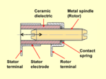 Rotary tubular piston, change of capacitance by changing the piston electrode overlap by inserting
 -
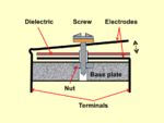 Squeezer, change of capacitance by changing the electrodes distance
![Rotary plate capacitor, change of capacitance by changing the electrodes overlap by rotation[12]](/wiki/File:Forgokondenzator_rajz_en.svg)


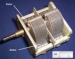
The most common form of mechanically controlled variable capacitors consists out of an arrangement of a group of metal plates on a rotary axis (“rotor”) that are positioned in the gaps between a set of stationary metal plates (“stator”) so that the area of overlap can be changed by rotating the axis. By the mechanical adjusted amount of plate surface overlap area the capacitance value will be changed. Air, vacuum, SF6 gas, ceramic, mica or plastic foils can be used as dielectric material.
Mechanically adjustable variable capacitors which changing the electrode distance to each other (squeezers or sliders) may be found in resonant loop antennas or early crystal radios.
| Dielectric- material |
Rel. permittivity εr at 1 kHz |
Breakdown voltage kV/mm |
|---|---|---|
| Vacuum | 1 | 20…500 |
| Air | 1 | 2…5 |
| Sulfur hexafluoride (SF6) | 2 | 8 |
| Mica | 7 | 25…200 |
| Ceramic class 1 | 6…200 | 20 |
| Ceramic class 2 | 100...1000 | 25 |
| Sapphire (Al2O3) | 8.9…11.1 | 700…1000 |
| Phenolic paper | 4 | 20…80 |
| Polycarbonate (PC) | 3,0 | 35…535 |
| Polyester (PET) | 3,3 | 25…580 |
| Polyethylene naphthalate (PEN) | 3,0 | 25 … 500 |
| Polypropylene (PP) | 2,2 | 100…650 |
| Polytetrafluoroethylene (PTFE) | 2,1 | 100…250 |
- Measuring the capacitance value of a tuning capacitor
-
 Cmin = 29 pF
 -
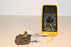 C = 269 pF
 -
 Cmax = 520 pF


History[edit]
- Crystal radio receiver
-
![Direct-coupled crystal radio circuit with a switched coil (L1) and a tuning capacitor (C2) for impedance matching[17]](//upload.wikimedia.org/wikipedia/commons/thumb/d/d1/Crystal_radio_with_impedance_matching.svg/191px-Crystal_radio_with_impedance_matching.svg.png) Direct-coupled crystal radio circuit with a switched coil (L1) and a tuning capacitor (C2) for impedance matching[17]
Direct-coupled crystal radio circuit with a switched coil (L1) and a tuning capacitor (C2) for impedance matching[17] -
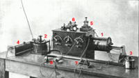 Early crystal radio receiver with adjustable antenna coupling transformer (1) and two tuning capacitors (2), (3)
![Direct-coupled crystal radio circuit with a switched coil (L1) and a tuning capacitor (C2) for impedance matching[17]](/wiki/File:Crystal_radio_with_impedance_matching.svg)

With the development of wireless telegraphy by Guglielmo Marconi and others from 1896 onwards, it became necessary to be able to adjust the used frequency within narrow limits, as well as in the transmitter as in the receiver devices. These frequency generated by a resonant circuit (consisting of a coil and a capacitor) could be influenced either by changing the coil inductance or by changing the capacitors capacitance. First widely used type of radio receivers at the beginning of the 20th century were crystal radios, which are mostly equipped with switched coils to adjust the frequency. However, this solution was large and less accurately. A more precise solution was given by adding a capacitor which capacitance can be changed. The first type of variable capacitor with two sets of parallel metal plates, one of them is fixed and the other moves on an axis, interleaving itself with the fixed set was invented by the Hungarian engineer Dezső Korda. He received a German patent for the invention on 13th December 1893.[18] This first tuning capacitor was improved for various functions of capacitance vs. angle by choosing the shape of the rotary plates by Adolf Koepsel in 1901.[19][20]
- Early tuning capacitors
-
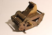 Tuning capacitor out of the 1920 years
 -
 Tuning capacitor with phenolic paper dielectric
 -
 Tuning capacitor with closed housing to protect the air dielectric capacitor against dust and humidity


.jpg)
The rapidly growing commercial radio broadcasting starts the development of a broad range of mechanical adjustable tuning capacitors. Air dielectric tuning capacitors require a relatively large amount of space because of the necessary plate spacing, and require a mechanically stable construction which caused considerable costs. Smaller and also cheaper solutions were sought even in the early days of the new radio technology. Smaller casings with the same capacitance range could be achieved by another dielectric with higher permittivity. Sheet mica was used already in the electrical industries. It is up to now a good electrical insulator, and could to be cut, punched, stamped, and machined to close tolerances. However, mica is expensive and sensitive against rubbing in rotating applications. The developments with mica are not very successful, however, phenolic paper was a good alternative. Tuning capacitors with phenolic paper dielectric mounted in hard paper housings were used until the 1970s.
The Audion vacuum tube invented by Lee De Forest in 1906 was the first practical amplifying device and revolutionized radio receivers.[21] The development of amplitude modulation (AM) around 1915 which could carry audio (sound) and vacuum tube transmitters during World War I, and the availability of cheap receiving tubes after the war, set the stage for the start of AM broadcasting, which sprang up spontaneously around 1920. At that time, crystal radios were superseded by superheterodyne receiver (often shortened to superhet), which is a type of radio receiver that uses frequency mixing to convert a received signal to a fixed intermediate frequency (IF) which can be more conveniently processed than the original carrier frequency. The use of an intermediate frequency generates a demand for another type of variable capacitors, which are intended for one adjustment of the IF only, at the initially calibrating of radios after manufacturing. These trimmer capacitors could be smaller and lesser robust, and a whole series of different versions have been developed over the years.
- Miscellaneous trimmer capacitors
-
 “Squeezer“, trimmer capacitor for varying the plate distance
 -
 Air-dielectric trimmer, squeezer, ceramic disc trimmer, ceramic and polystyrene tubular trimmer
 -
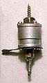 Concentric tubular cap type trimmer
 -
 Air dielectric plate trimmer capacitor


Variable capacitors for frequency tuning, however, were not only required for the receiver side. The exact frequency had to be adjusted on the transmitter side as well. For the relatively small power demand of the early transmitters, the air dielectric tuning capacitors already used for the receiver side were sufficient enough. With increasing transmitter power, however, the resonant circuit voltage increased, and as a result these variable capacitors became ever larger. New solutions have been developed with other dielectric materials. The mechanics of the rotating tuning capacitors were packed, for example, in housings filled with insulating oil.[22] Until today, however, vacuum or with the protective gas SF6 filled variable capacitors have been used.
- Tuning capacitors for transmitter side
-
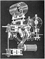 A tuned RF amplifier module for a radio transmitter, from 1938. This consists of two power triode tubes and a tank circuit consisting of a high Q coil (top) and a variable air-dielectric tuning capacitor (center).
 -
 Tunable variable vacuum capacitor for voltagen up to 40 kV


Tuning capacitors[edit]

In the early radios the multiple tuned circuits required multiple knobs to be adjusted to tune in a new station. One of the most important ease-of-use innovations was "single knob tuning", achieved by linking the tuning capacitors together mechanically.[23][24]
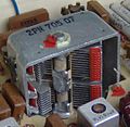
- single knob double-tuning capacitor for two bandpass filters
-
 Block diagram of a tuned radio frequency receiver with two bandpass filters must be tuned together simultaneously
 -
 Double-tuning capacitor which are ganged together so that the capacitance of two bandpass filters can be changed simultaneously
 -
 Double-tuning capacitor for tuning together with two trimmer capacitors for fine-tuning adjustment


References[edit]
- ^ Comet, Variable Capacitors, Variable Capacitors
- ^ Qizheng Gu, RF Tunable Devices and Subsystems: Methods of Modeling, Analysis, and Applications, Springer International Publishing, ISBN 978-3-319-09924-8
- ^ Gennum, Applications, Processing and Integration Options for High Dielectric Constant Multi-Layer Thin-Film Barium Strontium Titanate (BST) Capacitors
- ^ R. A. York, Tunable Dielectrics for RF Circuits
- ^ M.P.J. Tiggelman Thin Film Barium Strontium Titanate Capacitors for Tunable RF Front-end Application
- ^ ST’s Parascan™ Tunable Integrated Capacitors (STPTIC) Tunable Integrated Capacitors
- ^ IT Wissen, DTC (digitally tunable capacitor)
- ^ S. Lucyszyn, Review of radio frequency microelectromechanical systems technology, IEEE 2004, IEE Proceedings online no .20040405 doi:10.1049/ip-smt:20040405 Review of radio frequency microelectromechanical systems technology
- ^ Ch. Goldsmith, A. Malczewski, Z. Yao, S. Chen, J. Ehmke, D. Hinzel, Raytheon Systems Corporation, RF MEMs Variable Capacitors for Tunable Filters
- ^ The abbreviation "trimmer", which stands for a trimming capacitor, can lead to confusion. It is also used for "potentiometers" in the field of electronics.
- ^ J. J. Carr, RF Components and Circuits, ISBN: 0 7506 48449, Padder page 285, 285 [1]
- ^ Capacitor Guide, Air Capacitor Capacitor Guide, Air Capacitor
- ^ Handbuch der Elektronik (in German), München: Franzis Verlag GmbH, 1979, ISBN 3-7723-6251-6
- ^ WIMA, Characteristics of Metallized Film Capacitors in Comparison with Other Dielectrics
- ^ Epcos TDK, Film Capacitors, General technical information (PDF; 1,3 MB), abgerufen am 4. Dezember 2016
- ^ AVX, Dielectric Comparison Chart (PDF; 157 kB)
- ^ Klase, Alan R. (1998). "Crystal Set Design 102". Skywaves. Alan Klase personal website. Retrieved 2017-01-10.
- ^ George Washington Pierce: Principles of wireless telegraphy, McGraw-Hill book company, New York, 1910, p. 114. (Photo of rotary capacitor of Korda)
- ^ Die wahre Geschichte des Drehkondensators, Redaktionsbüro Peter von Bechen, 16. März 2014, Der Beitrag Dr. Adolf Koepsels zur Entwicklung der Funktechnik [2]
- ^ Photo collection of historical tuning capacitors. Jogis Röhrenbude
- ^ Lee, Thomas H. (2004) The Design of CMOS Radio Frequency Integrated Circuits, 2nd Ed., p. 9-11
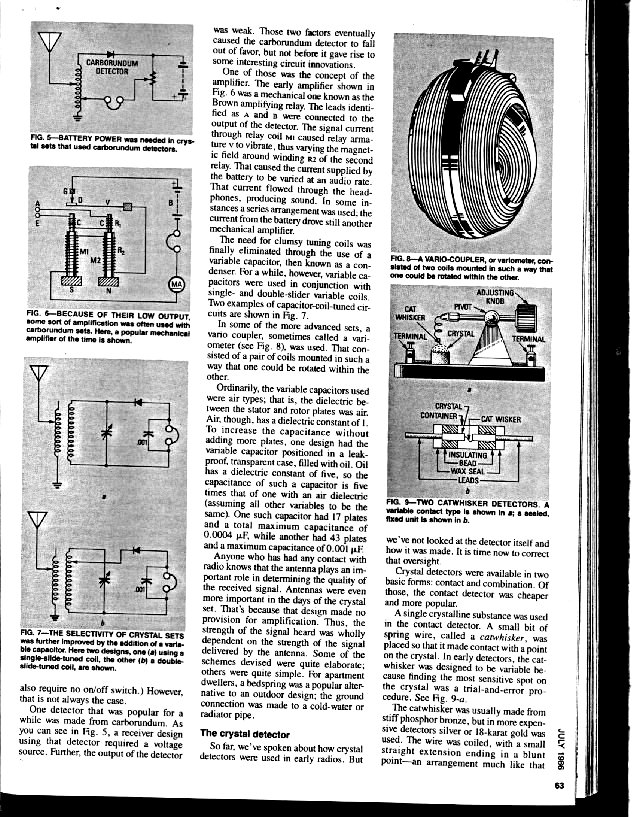
- ^ Clifford, Martin (July 1986). "The early days of radio". Radio Electronics: 61–64. Retrieved 2017-01-12. on Stay Tuned website
- ^ Wurtzler, Steve J. (2007). Electric Sounds: Technological Change and the Rise of Corporate Mass Media. Columbia Univ. Press. pp. 147–148. ISBN 023151008X.
- ^ Nebeker, Frederik (2009). Dawn of the Electronic Age: Electrical Technologies in the Shaping of the Modern World, 1914 to 1945. John Wiley and Sons. pp. 159–160. ISBN 0470409746.