
User:4throck/sandbox

Edit[edit]
| Color code | Color | Luminance | Chrominance | Y | R-Y (Pr) | B-Y (Pb) |
|---|---|---|---|---|---|---|
| 0 | transparent | - | - | - | - | - |
| 1 | black | 0% | - | 0% | 47% | 47% |
| 2 | medium green | 53% | 53% | 53% | 7% | 20% |
| 3 | light green | 67% | 40% | 67% | 17% | 27% |
| 4 | dark blue | 40% | 60% | 40% | 40% | 100% |
| 5 | light blue | 53% | 53% | 53% | 43% | 93% |
| 6 | dark red | 47% | 47% | 47% | 83% | 30% |
| 7 | cyan | 67% | 60% | 73% | 0% | 70% |
| 8 | medium red | 53% | 60% | 53% | 93% | 27% |
| 9 | light red | 67% | 60% | 67% | 93% | 27% |
| 10 | dark yellow | 73% | 47% | 73% | 57% | 7% |
| 11 | light yellow | 80% | 33% | 80% | 57% | 17% |
| 12 | dark green | 46% | 47% | 47% | 13% | 23% |
| 13 | magenta | 53% | 40% | 53% | 73% | 67% |
| 14 | gray | 80% | - | 80% | 47% | 47% |
| 15 | white | 100% | - | 100% | 47% | 47% |
colors[edit]
SAM Coupé color palette and bitmask 02 12 102 112 1002 1012 1102 1112 10002 10012 10102 10112 11002 11012 11102 11112 100002 100012 100102 100112 101002 101012 101102 101112 110002 110012 110102 110112 111002 111012 111102 111112 1000002 1000012 1000102 1000112 1001002 1001012 1001102 1001112 1010002 1010012 1010102 1010112 1011002 1011012 1011102 1011112 1100002 1100012 1100102 1100112 1101002 1101012 1101102 1101112 1110002 1110012 1110102 1110112 1111002 1111012 1111102 1111112 10000002 10000012 10000102 10000112 10001002 10001012 10001102 10001112 10010002 10010012 10010102 10010112 10011002 10011012 10011102 10011112 10100002 10100012 10100102 10100112 10101002 10101012 10101102 10101112 10110002 10110012 10110102 10110112 10111002 10111012 10111102 10111112 11000002 11000012 11000102 11000112 11001002 11001012 11001102 11001112 11010002 11010012 11010102 11010112 11011002 11011012 11011102 11011112 11100002 11100012 11100102 11100112 11101002 11101012 11101102 11101112 11110002 11110012 11110102 11110112 11111002 11111012 11111102 11111112
Hα recombination line radiation at a wavelength of 656.3 nm. - sRGB value: #ff0000[1]
(O III in spectroscopic notation). Its emission forbidden lines in the visible spectrum fall primarily at the wavelength 500.7 nm, and secondarily at 495.9 nm.
sRGB value: #00ff87; sRGB value: #00ffc0
Forbidden lines of nitrogen ([N II] at 654.8 and 658.4 nm), sulfur ([S II] at 671.6 and 673.1 nm), and oxygen ([O II] at 372.7 nm, and [O III] at 495.9 and 500.7 nm) are commonly observed in astrophysical plasmas.
The following table lists the internal signals and shows an approximation of the generated colors, as seen on a web standard sRGB monitor. Colors could be different when seen on an analog PAL CRT television.
| Color | R | G | B | INV | Luminance (%) | Chroma (º) | Chroma (%) |
|---|---|---|---|---|---|---|---|
| Black | 0 | 0 | 0 | 0 | 0.0 | - | - |
| Red | 1 | 0 | 0 | 0 | 22.5 | 103 | 48 |
| Green | 0 | 1 | 0 | 0 | 44.0 | 241 | 44 |
| Yellow | 1 | 1 | 0 | 0 | 66.5 | 167 | 33 |
| Blue | 0 | 0 | 1 | 0 | 8.5 | 347 | 33 |
| Magenta | 1 | 0 | 1 | 0 | 31.0 | 61 | 44 |
| Cyan | 0 | 1 | 1 | 0 | 52.5 | 283 | 48 |
| White | 1 | 1 | 1 | 0 | 100.0 | - | - |
| Grey | 0 | 0 | 0 | 1 | 75.0 | - | - |
| Cyan | 1 | 0 | 0 | 1 | 52.5 | 283 | 24 |
| Magenta | 0 | 1 | 0 | 1 | 31.0 | 61 | 22 |
| Blue | 1 | 1 | 0 | 1 | 8.5 | 347 | 17 |
| Yellow | 0 | 0 | 1 | 1 | 66.5 | 167 | 17 |
| Green | 1 | 0 | 0 | 1 | 44.0 | 241 | 22 |
| Red | 0 | 1 | 1 | 1 | 22.5 | 103 | 24 |
| Black | 1 | 1 | 1 | 1 | 0.0 | - | - |
An alternate configuration of the chip allows it to output 95% luminance color bars - similar to BBC colour bars, more suited for usage in teletext decoders.[2]
| Color | R | G | B | INV | Luminance (%) | Chroma (º) | Chroma (%) |
|---|---|---|---|---|---|---|---|
| Black | 0 | 0 | 0 | 0 | 0.0 | - | - |
| Red | 1 | 0 | 0 | 0 | 47.5 | 103 | 48 |
| Green | 0 | 1 | 0 | 0 | 69 | 241 | 44 |
| Yellow | 1 | 1 | 0 | 0 | 91.5 | 167 | 33 |
| Blue | 0 | 0 | 1 | 0 | 33.5 | 347 | 33 |
| Magenta | 1 | 0 | 0 | 0 | 56 | 61 | 44 |
| Cyan | 0 | 1 | 1 | 0 | 77.5 | 283 | 48 |
| White | 1 | 1 | 1 | 0 | 100.0 | - | - |
| Grey | 0 | 0 | 0 | 1 | 75.0 | - | - |
| Cyan | 1 | 0 | 0 | 1 | 77.5 | 283 | 24 |
| Magenta | 0 | 1 | 0 | 1 | 56 | 61 | 22 |
| Blue | 1 | 1 | 0 | 1 | 33.5 | 347 | 17 |
| Yellow | 0 | 0 | 1 | 1 | 91.5 | 167 | 17 |
| Green | 1 | 0 | 0 | 1 | 69 | 241 | 22 |
| Red | 0 | 1 | 1 | 1 | 47.5 | 103 | 24 |
| Black | 1 | 1 | 1 | 1 | 0.0 | - | - |
References[edit]
- ^ "Light wavelength to RGB Converter". www.johndcook.com. Retrieved 2023-04-17.}}
- ^ a b c TEA1002 PAL Colour Encoder and Video Summer. Mullard. 1982.
}}
- Revista Micro Sistemas, p. 85. Julho de 1983.
Extended Graphics Array[edit]

The Extended Graphics Array (XGA) is an IBM display standard introduced in 1990.[2] Later it became the most common appellation of the 1024 × 768 pixels display resolution[3], but the official definition is broader than that.[4] It was not a new and improved replacement for Super VGA, but rather became one particular subset of the broad range of capabilities covered under the "Super VGA" umbrella.
All standard XGA modes have a 4:3 aspect ratio with square pixels, although this does not hold for certain standard VGA and third-party extended modes (640 × 400, 1280 × 1024).
XGA should not be confused with EVGA (Extended Video Graphics Array), a contemporaneous VESA standard that also has 1024 × 768 pixels. It should also not be confused with the Expanded Graphics Adapter, a peripheral for the IBM 3270 PC which can also be referred to as XGA.[5]
History[edit]
It was initially built into the new PS/2 Model 90 and 90 XP, and was also available as an upgrade for existing PS/2 systems, as the “IBM PS/2 XGA Display Adapter/A”.
The initial version of XGA (and its predecessor, the IBM 8514/A) expanded upon IBM's older VGA by adding support for four new screen modes (three, for the 8514/A), including one new resolution:[6]
- 640 × 480 pixels in 8 bit/px (256 color) palette-indexed mode.
- 640 × 480 pixels in direct 16 bits-per-pixel (65,536 color) RGB hi-color (required 1 MB video memory option)
- 1024 × 768 pixels with a 16-color (4 bit/px) palette, using a low frequency interlaced refresh rate
- 1024 × 768 pixels with a 256-color (8 bit/px) palette, using a low frequency interlaced refresh rate (required 1 MB VRAM[7])
Like the 8514, XGA offered fixed function hardware acceleration to offload processing of 2D drawing tasks. Both adapters allowed offloading of line-draw, bitmap-copy (BitBlt), and color-fill operations from the host CPU. XGA's acceleration was faster than 8514's, and more comprehensive, supporting more drawing primitives, the VGA-res hi-color mode, versatile "brush" and "mask" modes, system memory addressing functions, and a single simple hardware sprite typically used to provide a low CPU load mouse pointer. It was also capable of wholly independent function, as it incorporated support for all existing VGA functions and modes – the 8514 itself was a simpler add-on adapter that required a separate VGA to be present. As they were designed for use with IBM's range of fixed-frequency monitors, neither adapter offered support for 800 × 600 SVGA modes.
Software support included drivers for OS/2 1.2 and 1.3, Windows 2.1 and 3.0, and popular software packages like AutoCAD.[6]
XGA-2 , released in 1992, added a 24-bit DAC, but this was used only to extend the available master palette in 256-color mode, e.g. to allow true 256-greyscale output instead of the 64 grey levels previously available; there was still no direct True Color mode despite the adapter featuring enough default onboard VRAM (1 MB) to support it. Other improvements included the provision of the previously missing 800 × 600 resolution (using an SVGA or multisync monitor) in up to 65,536 colors, faster screen refresh rates in all modes (including non-interlace, flicker-free output for 1024 × 768), and improved accelerator performance and versatility.
IBM licensed the XGA technology and architecture to certain third-party hardware developers, and its characteristic modes (although not necessarily the accelerator functions, nor the MCA data-bus interface) were aped by many others. These accelerators typically did not suffer from the same limitations on available resolutions and refresh rate, and featured other now-standard modes like 800 × 600 (and 1280 × 1024) at various color depths (up to 24 bit/px) and interlaced, non-interlaced and flicker-free refresh rates even before the release of the XGA-2. Category:6809-based home computers Category:Thomson computers
References:[edit]
- ^ "XGA Logo". Paul Rand Foundation. Retrieved September 25, 2021.
- ^ IBM US (October 30, 1990). "IBM PS/2 XGA DISPLAY ADAPTER/A - IBM Announcement Letter Number 190-182". ardent-tool.com.
- ^ "XGA Full Form". GeeksforGeeks. 2020-05-13. Retrieved 2022-12-12.
- ^ Team, AnimationXpress (2006-07-19). "XGA (Extended Graphics array) -". Retrieved 2022-12-12.
- ^ IBM 3270 Workstation Program User's Guide and Reference (PDF). International Business Machines Corporation. 1987. p. GL-17. Retrieved 2014-01-23.
- ^ a b Necasek, Michal. "The XGA Graphics Chip". The OS/2 Museum. Retrieved 2013-08-01.
- ^ Necasek, Michal. "The 8514/A Graphics Accelerators". The OS/2 Museum. Retrieved 2013-08-01.
Television systems before 1940[edit]

Table of systems
| Introduction Year | Country | Technology | Lines | Frame Rate | Aspect Ratio | Channel Bandwidth
(MHz) |
Line
Frequency (Hz) |
Station | Notes and references |
|---|---|---|---|---|---|---|---|---|---|
| 1930 | France | Mechanical | 30 | 12.5 | |||||
| 1932 | France | Mechanical | 60 | 12.5 | 3:7 | Vertical aspect ratio, sound, and live images[1]; approximate resolution of ~35x60 | |||
| 1935 | France | Mechanical | 180 | 25 | [2][1][3] | ||||
| 1936 | France | Electronic | 180 | 25 | 4500 | [3][4] | |||
| 1937 | France | Electronic | 455 | 25 | 7 | Eiffel Tower | Developed by Rene Barthelemy[5][6][3][7][8][9][10] | ||
| 1941 | France | Electronic | 441 | 25 | 1.15:1 | 7 | 11025 | Fernsehsender Paris | By 1941 the "Fernsehsender Paris" station transmitted from the Eiffel Tower in Paris using the German 441 lines system. Used same broadcast frequencies as the previous 455-line system[7][11][10] |
| 1932 | Germany | Mechanical | 48 | 25 | 4:3 | Sound, talking movies; approximate resolution of ~64x48 | |||
| 1932 | Germany | Mechanical | 60 | 25 | 4:3 | Test movies and live images; approximate resolution of ~83x60 | |||
| 1932 | Germany | Electronic | 90 | ||||||
| 1935 | Germany | Electronic | 180 | 25 | Reichspost cable network | [12][13][14][2][15][16] | |||
| 1936 | Germany | Electronic | 375 | 25 | Berlin-Witzleben, Reichspost cable network | [14][17][14][18][19] | |||
| 1937 | Germany | Electronic | 441 | 25 | 1.15:1 | 4 | 11025 | Reichspost cable network | [20][7][21][20][21][21] |
| 1940 | Germany | Electronic | 1000 | Used for projection, not for direct viewing using a CRT. Limited to experiments in Reichspost laboratories. | |||||
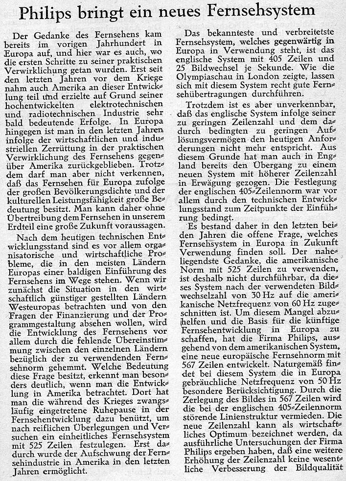
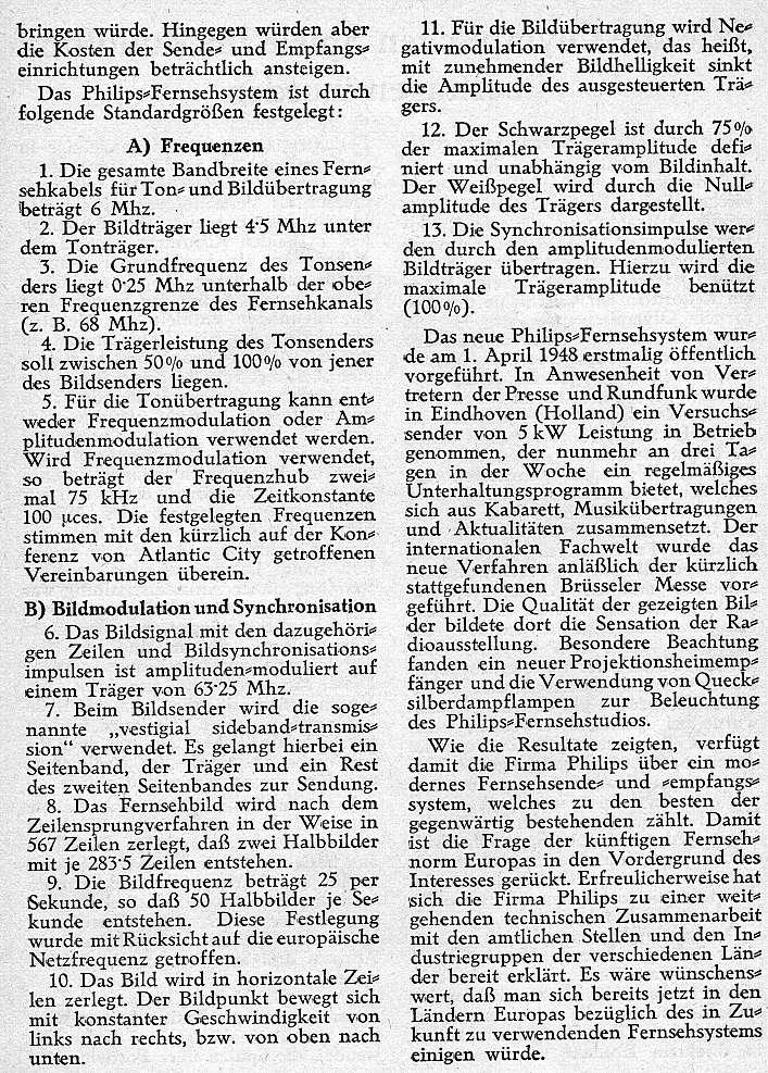
| 1930s | Netherlands | Electronic | 441 | 25 | 11025 | ||||
| 1938 | Netherlands | Electronic | 567 | 25 | 6 | 14175 | [22][23][24][25][26] | ||
| 1937 | Poland | Mechanical | 120 | Warsaw, test movies and live images from a studio | |||||
| 1939 | Poland | Electronic | 343 | Under development and was publicly demonstrated during the Radio Exhibition in Warsaw in August 1939, regular operations planned to start at the beginning of 1940, work stopped because of the outbreak of World War II. | |||||
| 1932 | Switzerland | Mechanical | 30 | 16.6 | 4:3 | Test broadcasts, approximate resolution of ~40×30 | |||
| 1930s | Vatican City | Experimental transmissions | |||||||
| 1932 | Italy | Mechanical | 60 | 20 | 4:3 | Test movies and live images, approximate resolution of ~45x60 | |||
| 1937 | Italy | Electronic | 375 | 25 | 4:3 | Rome | daily from Rome, between 6pm and 9.30pm on 6.9 meters with a power of 2 kW | ||
| 1939 | Italy | Electronic | 441 | 25 | 4:3 | Rome, Milan | regular service from Rome and Milan. 2 kW transmission power on VHF 45 MHz[7] | ||
| 1926 | UK | Mechanical | 30 | 5 | Baird mechanical; black-and-white experimental transmissions. On January 26, 1926, Baird demonstrated the transmission of images of real human faces for 40 distinguished scientists of the Royal Institution. This is widely regarded as being the world's first public television demonstration. | ||||
| 1928 | UK | Mechanical | 30 | 5 | Baird mechanical; first experimental colour TV transmissions[27] | ||||
| 1932 | UK | Mechanical | 30 | 12.5 | 3:7 | Baird mechanical; vertical aspect ratio, approximate resolution of ~70×30; sound, live TV from studio, first outdoor remote broadcasts of the Derby[28] | |||
| 1936 | UK | Mechanical | 240 | 25 | 6000 | BBC | Used from November 1936 to February 1937 at the Crystal Palace studios, and later on BBC television broadcasts. For action shots (as opposed to a seated presenter), the mechanical system did not scan the televised scene directly. Instead, a 17.5mm film was shot, rapidly developed, and then scanned while the film was still wet. | ||
| 1936 | UK | Electronic | 405 | 25 | 5:4 | 5 | 10125 | BBC | Used by the BBC Alexandra Palace television station initially from November 1936 to 1939 and then 1946 to 1985 (interruption due to Second World War).[29][30] |
| 1938 | UK | Mechanical | 120 | Baird, world's first color broadcast on February 4, 1938, from Baird's Crystal Palace studios to a projection screen at London's Dominion Theatre.[31] | |||||
| 1932 | USSR | Mechanical | 30 | 12.5 | Approximately ~40x30, test movies and live images | ||||
| 1935 | USSR | Electronic | 180 | 25 | St. Petersburg | ||||
| 1937 | USSR | Electronic | 240 | 25 | St. Petersburg | ||||
| 1938 | USSR | Electronic | 343 | 25 | Moscow, RCA provided broadcast equipment and documentation for TV sets | ||||
| 1933 | USA | 240 | |||||||
| 1936 | USA | Electronic | 343 | limited public demonstrations in New York City (RCA) and Philadelphia (Philco). | |||||
| 1937 | USA | Electronic | 441 | 30 | 6 | 13230 | NBC | RCA | |
| 1937 | USA | Electronic | 605 | Proposed by Philco | |||||
| 1941 | USA | Electronic | 375 | 60 | 22500 | WCBW (CBS) | Field sequential color, tested by WCBW CBS in New York.[32][33][34] | ||
| 1926 | Japan | Electronic | 40 | On December 25, 1926, Kenjiro Takayanagi demonstrated a television system with a 40-line resolution that employed a Nipkow disk scanner and CRT display at Hamamatsu Industrial High School in Japan. This prototype is still on display at the Takayanagi Memorial Museum at Shizuoka University, Hamamatsu Campus.[35] | |||||
| 1927 | Japan | Electronic | 100 | By 1927, Takayanagi improved the resolution to 100 lines.[36][37] |
References[edit]
- ^ a b Herbert, Stephen (2004). A History of Early Television. ISBN 9780415326674.
- ^ a b "Grammont Prewar Sets". www.earlytelevision.org.
- ^ a b c "Early French Broadcasting". www.earlytelevision.org.
- ^ "Toute La Radio" (PDF). Toute La Radio (24). 1936.
- ^ "Barthelemy". www.earlytelevision.org.
- ^ "Emyradio Prewar Sets". www.earlytelevision.org.
- ^ a b c d "405 Alive - FAQ - 405-Line Television in History". www.bvws.org.uk.
- ^ Brice, Richard (June 14, 2003). "Newnes Guide to Digital TV". Newnes – via Google Books.
- ^ Gripsrud, Jostein; Weibull, Lennart (June 14, 2010). "Media, Markets & Public Spheres: European Media at the Crossroads". Intellect Books – via Google Books.
- ^ a b "405 Alive - FAQ - 405-Line Television in History". www.bvws.org.uk.
- ^ "Prewar European Stations". www.earlytelevision.org.
- ^ "Telefunken Prewar Sets". www.earlytelevision.org.
- ^ Larrasa, Miranda (2016). The Olympic Museum (ed.). "Broadcasting the Olympic Games, the Media and the Olympic Games - Television Broadcasting" (PDF). Olympics. p. 4.
- ^ a b c "Berlin Olympics Television 1936".
- ^ "Gerolf Poetschke's Site Telefunken FE III". www.earlytelevision.org.
- ^ "Gerolf Poetschke's Site Fernseh Tischmodell". www.earlytelevision.org.
- ^ Beauchamp, K. G.; Beauchamp, Kenneth George (May 27, 1997). Exhibiting Electricity. IET. ISBN 9780852968956 – via Google Books.
- ^ Marshall, Paul (2011). Inventing Television: Transnational Networks of Co-operation and Rivalry, 1870-1936 (PDF) (Thesis). University of Manchester.
- ^ "1937 TV". www.thevalvepage.com.
- ^ a b "R.T.Russell: Colour Test Card Generator". bbcbasic.uk.
- ^ a b c "Einheits-Fernseh-Empfänger E l" (PDF). aobauer.home.xs4all.nl. pp. 320–321. Archived (PDF) from the original on 28 March 2022.
- ^ "Funktechnik- Philips bringt ein neues Fernsehsystem, Heft 2 1948".
- ^ "Funktechnik - Philips bringt ein neues Fernsehsystem, Heft 2 1948".
- ^ "Sistem masuk tunggal Z-Library". id.1lib.domains.
- ^ "Philips Netherland 567 line TV Standard" (in German). Radiomuseum.org. Retrieved 2011-06-20.
- ^ J. van der Mark (January 1938). "A transportable television installation" (PDF). Philips Technical Review. 3 (1): 2.
The installation is suitable for the broadcasting of 25 pictures per second, with 405 or 567 lines per complete picture, while interlaced scanning is employed. (If 567 lines are used, a frequency spectrum must be dealt with which extends from about 50 cycles per second to about 5 × 10⁶ cycles per second, for 405 lines the necessary frequency spectrum extends only to 2.5·106 cycles per second.
- ^ John Logie Baird, Television Apparatus and the Like, U.S. patent, filed in U.K. in 1928.
- ^ BAIRD, J.L. BAIRD (1933). "BBC Annual Report".
- ^ "First Live BBC Recording". Alexandra Palace Television Society. Archived from the original on 4 April 2005. Retrieved 26 April 2005.
- ^ Alan Pemberton (2003-07-01). "World Analogue Television Standards and Waveforms - Line Standards". Pembers.freeserve.co.uk. Archived from the original on 3 April 2007. Retrieved 2014-05-20.
- ^ Baird Television: Crystal Palace Television Studios. Previous color television demonstrations in the U.K. and U.S. had been via closed circuit.
- ^ "CBS Color Television System Chronology". September 22, 2013. Archived from the original on 2013-09-22.
- ^ "DuMont 183". www.earlytelevision.org.
- ^ Abramson, Albert (May 27, 1955). "Electronic Motion Pictures". University of California Press – via Google Books.
- ^ Kenjiro Takayanagi: The Father of Japanese Television, NHK (Japan Broadcasting Corporation), 2002, retrieved 2009-05-23.
- ^ High Above: The untold story of Astra, Europe's leading satellite company, page 220, Springer Science+Business Media
- ^ "TV's Japanese Dad?". Popular Photography. November 1990. p. 5.
edit[edit]
MDA[edit]
| 01 | 02 | 03 | 04 | 05 | 06 | 07 | 09 | 0A | 0B | 0C | 0D | 0E | 0F | 10 | 11 | 12 | 13 | 14 | 15 | 16 | 17 | 18 | 19 | 1A | 1B | 1C | 1D | 1E | 1F | ||
| 20 | 21 | 22 | 23 | 24 | 25 | 26 | 27 | 28 | 29 | 2A | 2B | 2C | 2D | 2E | 2F | 30 | 31 | 32 | 33 | 34 | 35 | 36 | 37 | 38 | 39 | 3A | 3B | 3C | 3D | 3E | 3F |
| 40 | 41 | 42 | 43 | 44 | 45 | 46 | 47 | 48 | 49 | 4A | 4B | 4C | 4D | 4E | 4F | 50 | 51 | 52 | 53 | 54 | 55 | 56 | 57 | 58 | 59 | 5A | 5B | 5C | 5D | 5E | 5F |
| 60 | 61 | 62 | 63 | 64 | 65 | 66 | 67 | 68 | 69 | 6A | 6B | 6C | 6D | 6E | 6F | 70 | 71 | 72 | 73 | 74 | 75 | 76 | 77 | 78 | 79 | 7A | 7B | 7C | 7D | 7E | 7F |
| 81 | 82 | 83 | 84 | 85 | 86 | 87 | 89 | 8A | 8B | 8C | 8D | 8E | 8F | 90 | 91 | 92 | 93 | 94 | 95 | 96 | 97 | 98 | 99 | 9A | 9B | 9C | 9D | 9E | 9F | ||
| A0 | A1 | A2 | A3 | A4 | A5 | A6 | A7 | A8 | A9 | AA | AB | AC | AD | AE | AF | B0 | B1 | B2 | B3 | B4 | B5 | B6 | B7 | B8 | B9 | BA | BB | BC | BD | BE | BF |
| C0 | C1 | C2 | C3 | C4 | C5 | C6 | C7 | C8 | C9 | CA | CB | CC | CD | CE | CF | D0 | D1 | D2 | D3 | D4 | D5 | D6 | D7 | D8 | D9 | DA | DB | DC | DD | DE | DF |
| E0 | E1 | E2 | E3 | E4 | E5 | E6 | E7 | E8 | E9 | EA | EB | EC | ED | EE | EF | F0 | F1 | F2 | F3 | F4 | F5 | F6 | F7 | F8 | F9 | FA | FB | FC | FD | FE | FF |
The attribute bytes mostly behave like a bitmap:
- Bits 0-2: 1 => underline, other values => no underline.
- Bit 3: High intensity.
- Bit 7: Blink
but there are eight exceptions:
- Attributes 00h, 08h (0000 1000), 80h (1000 0000) and 88h (1000 1000) display as black space.
- Attribute 70h (0111 0000) displays as black on green.
- Attribute 78h (0111 1000) displays as dark green on green. In fact, depending on timing and on the design of the monitor, it may have a bright green 'halo' where the dark green and bright green bits meet.
- Attribute F0h (1111 0000) displays as a blinking version of 70h (if blinking is enabled); as black on bright green otherwise.
- Attribute F8h (0111 1000) displays as a blinking version of 78h (if blinking is enabled); as dark green on bright green otherwise.
| Background | Foreground | Result | ||||||||
|---|---|---|---|---|---|---|---|---|---|---|
| 7 | 6 | 5 | 4 | 3 | 2 | 1 | 0 | |||
| IB | R | G | B | I | R | G | B | |||
| 0 | 0 | 0 | 0 | 1 | 0 | 0 | 0 |
|
Invisible | |
| 1 | 0 | 0 | 0 | 0 | 0 | 0 | 0 |
|
Invisible | |
| 1 | 0 | 0 | 0 | 1 | 0 | 0 | 0 |
|
Invisible | |
| 0 | 0 | 0 | 0 | 0 | 0 | 0 | 1 | Underline | ||
| 0 | 0 | 0 | 0 | 0 | 0 | 1 | 0 | Normal | ||
| 0 | 1 | 1 | 1 | 0 | 0 | 0 | 0 |
|
Reverse | |
| 0 | 1 | 1 | 1 | 1 | 0 | 0 | 0 |
|
Reverse, high-intensity foreground | |
| 0 | 1 | 1 | 1 | 0 | 0 | 0 | 0 |
|
Reverse, high-intensity foreground, high-intensity background | |
| 1 | 1 | 1 | 1 | 0 | 0 | 0 | 0 |
|
Reverse, high-intensity background | |
| Attribute | Display |
|---|---|
| Invisible | Invisible
|
| Normal | Normal
|
| Underline | Underline
|
| Bright | Bright
|
| Bright Underline | Bright Underline
|
| Reverse Video | Reverse Video
|
| Invisible Reverse | Invisible Reverse
|
http://www.techhelpmanual.com/87-screen_attributes.html
| Background | Foreground | ||||||||
|---|---|---|---|---|---|---|---|---|---|
| Bl | R | G | B | I | R | G | B | ||
| 7 | 6 | 5 | 4 | 3 | 2 | 1 | 0 | Monochrome Monitor | TTL Monochrome Monitor |
| 0 | 0 | 0 | 0 | 0 | 0 | 0 | 1 | - | Underline |
| 0 | 0 | 0 | 0 | 0 | 1 | 1 | 1 | Normal | Normal |
| 0 | 0 | 0 | 0 | 1 | 0 | 0 | 0 | Grey on black | Bright+Underline |
| 0 | 0 | 0 | 0 | 1 | 1 | 1 | 1 | Bold | Bold |
| 0 | 1 | 1 | 1 | 0 | 0 | 0 | 0 | Reverse | Reverse |
| 0 | 1 | 1 | 1 | 1 | 0 | 0 | 0 | Grey on White | Blink+Underline |
| 0 | 1 | 1 | 1 | 1 | 1 | 1 | 1 | Bright on White | Blink+normal |
| 1 | 0 | 0 | 0 | 0 | 1 | 1 | 1 | Blink+Normal | Blink+Bright+Underline |
| 1 | 0 | 0 | 0 | 1 | 1 | 1 | 1 | Blink+Bold | Blink+Bold |
  TTL Monochrome Monitors▲     █     Black-and-White Monitors
  ▄▄▄▄▄▄▄▄▄▄▄▄▄▄▄▄▄▄▄▄▄▄▄▄▄▄▄▄▄▄▄▄▄█▄▄▄▄▄▄▄▄▄▄▄▄▄▄▄▄▄▄▄▄▄▄▄▄▄▄▄▄▄▄▄▄▄
  01H underline                    █ 07H normal (white on black)
  07H normal (white on black)      █ 08H grey on black
  09H bright underline             █ 0fH bold (bright white on black)
  0fH bold (bright white on black) █ 70H reverse (black on white)
  70H reverse (black on white)     █ 78H grey on white
  81H blinking underline           █ 7fH bright white on white
  87H blinking normal              █ 87H blinking normal
  89H blinking bright underline    █ 8fH blinking bold
8fH blinking bold █
| Background | Foreground | Explanation |
|---|---|---|
| 0/3
0000 |
2/3
0001 |
Normal
▌ ░▒▓ |
| 0/3
0000 |
3/3
1111 |
High intensity
▌░▒▓ |
| 2/3
0111 |
0/3
0000 |
Reverse video
▌░▒▓ |
| 3/3
0111 |
1/3
1000 |
Reverse video, high intensity, blink set but disabled
▌░▒▓ |
| 2/3
0111 |
1/3
1000 |
Reverse video, high intensity
▌░▒▓ |
| 3/3
1111 |
0/3
0 000 |
Reverse video, blink set but disabled
▌░▒▓ |
UK101 Character Set[edit]
| 0 | 1 | 2 | 3 | 4 | 5 | 6 | 7 | 8 | 9 | A | B | C | D | E | F | |
|---|---|---|---|---|---|---|---|---|---|---|---|---|---|---|---|---|
| 0 | ⌃ | ≡ | ||||||||||||||
| 1 | ↑ | ↗ | → | ↘ | ↓ | ↙ | ← | ↖ | £ | |||||||
| 2 | ! | " | # | $ | % | & | ' | ( | ) | * | + | , | - | . | / | |
| 3 | 0 | 1 | 2 | 3 | 4 | 5 | 6 | 7 | 8 | 9 | : | ; | < | = | > | ? |
| 4 | @ | A | B | C | D | E | F | G | H | I | J | K | L | M | N | O |
| 5 | P | Q | R | S | T | U | V | W | X | Y | Z | [ | \ | ] | ^ | _ |
| 6 | a | b | c | d | e | f | g | h | i | j | k | l | m | n | o | |
| 7 | p | q | r | s | t | u | v | w | x | y | z | { | } | | | ÷ | |
| 8 | ||||||||||||||||
| 9 | ||||||||||||||||
| A | ◤ | |||||||||||||||
| B | ◢ | ◥ | ◣ | ⇒ | ⇐ | ⇔ | △ | ╳ | ╱ | ╲ | ||||||
| C | ┗ | ┏ | ┓ | ┛ | ||||||||||||
| D | √ | ∫ | ∙ | ≈ | ┻ | ┣ | ┳ | ┫ | ╋ | ╰ | ╭ | ╮ | ╯ | |||
| E | ♥ | ♣ | ♠ | ⯁ | ◄ | ► | ||||||||||
| F | α | ß | ω | 𝛿 | Ω | μ | π | Σ | λ | ϕ | θ | ε | ν | γ |
Test[edit]
Digital values from https://www.cypress.com/file/74746/download
| COLOR | RGB | 10-bit Y'CbCr | Approximate sRGB value |
|---|---|---|---|
| 100% White | 1 - 1 - 1 | 940-512-512 | 255-255-255 |
| 75% White | 0.75 - 0.75 - 0.75 | 721-512-512 | 191-191-191 |
| 75% Yellow | 0.75 - 0.75 - 0 | 646-176-567 | 191-191-0 |
| 75% Cyan | 0 - 0.75 - 0.75 | 525-625-176 | 0-191-190 |
| 75% Green | 0 - 0.75 - 0 | 450-289-231 | 0-191-0 |
| 75% Magenta | 0.75 - 0 - 0.75 | 335-735-793 | 191-0-192 |
| 75% Red | 0.75 - 0 - 0 | 260-399-848 | 191-0-1 |
| 75% Blue | 0 - 0 - 0.75 | 139-848-457 | 0-0-191 |
| -4% Black | -0.04 - -0.04 - -0.04 | 29-512-512 | -10 -10 -10 |
| 0% Black | 0 - 0 - 0 | 64-512-512 | 0-0-0 |
| +4% Black | 0.04 - 0.04 - 0.04 | 99-512-512 | 10-10-10 |
| -I | 0 - 0.2456 - 0.4125 | 231-624-390 | 0-63-105 |
| +Q | 0.2536 - 0 - 0.4703 | 177-684-591 | 65-0-120 |
Digital color bar values[edit]
After some searching, I was able to find references for digital values, for both SD and HD 100% and 75% bars.
- https://www.leaderamerica.com/pdf/vol03_no04.pdf
- https://www.itu.int/dms_pubrec/itu-r/rec/bt/R-REC-BT.1729-0-200504-I!!PDF-E.pdf
The first document shows the usage of signal analyzers (LV5100 for SD - http://www.valtechvideo.com/partneri/leader/LV5100D.pdf and LV5152 DA for HD - https://assets.tequipment.net/assets/1/26/Documents/Leader/lv-5152da_manual.pdf) with SD and HD patterns. Both SD and HD values for 75% and 100% bars are explicitly listed. Here's the explanation provided for the values shown:
For digital video sources, the 10-bit YCbCr values for color bars are diferent depending if we have a SD or HD signal[1]. SD values are based on the SMPTE formula for Y from the NTSC system ( Y = 0.299R + 0.587G + 0.114B)[1]. HD values are according to SMPTE RP-177 and 274M ( based on the formula Y= 0.2126R + 0.7152G + 0.722B)[1]
| SD 100%[2][3] | HD 100%[1][4] | SD 75%[5] | HD 75%[6] | ||||||||||||
|---|---|---|---|---|---|---|---|---|---|---|---|---|---|---|---|
| Y | Cb | Cr | Y | Cb | Cr | Y | Cb | Cr | Y | Cb | Cr | ||||
| White | 940 | 512 | 512 | White | 940 | 512 | 512 | White | 940 | 512 | 512 | White | 940 | 512 | 512 |
| Yellow | 840 | 64 | 585 | Yellow | 877 | 64 | 553 | Yellow | 646 | 176 | 567 | Yellow | 674 | 176 | 543 |
| Cyan | 678 | 663 | 64 | Cyan | 754 | 615 | 64 | Cyan | 525 | 625 | 176 | Cyan | 581 | 589 | 176 |
| Green | 578 | 215 | 137 | Green | 690 | 167 | 105 | Green | 450 | 289 | 231 | Green | 534 | 253 | 207 |
| Magenta | 426 | 809 | 887 | Magenta | 314 | 857 | 919 | Magenta | 335 | 735 | 793 | Magenta | 251 | 771 | 817 |
| Red | 326 | 361 | 960 | Red | 250 | 409 | 960 | Red | 260 | 399 | 848 | Red | 204 | 435 | 848 |
| Blue | 164 | 960 | 439 | Blue | 127 | 960 | 462 | Blue | 139 | 848 | 457 | Blue | 111 | 848 | 16 |
| Black | 64 | 512 | 512 | Black | 64 | 512 | 512 | Black | 64 | 512 | 512 | Black | 64 | 512 | 512 |
| SD 100%[1][3] | HD 100%[1][3] | SD 75%[1] | HD 75%[1] | ||||||||||||
| Y | Cb | Cr | Y | Cb | Cr | Y | Cb | Cr | Y | Cb | Cr | ||||
| White | 940 | 512 | 512 | White | 940 | 512 | 512 | White | 940 | 512 | 512 | White | 940 | 512 | 512 |
| Yellow | 840 | 64 | 585 | Yellow | 877 | 64 | 553 | Yellow | 646 | 176 | 567 | Yellow | 674 | 176 | 543 |
| Cyan | 678 | 663 | 64 | Cyan | 754 | 615 | 64 | Cyan | 525 | 625 | 176 | Cyan | 581 | 589 | 176 |
| Green | 578 | 215 | 137 | Green | 690 | 167 | 105 | Green | 450 | 289 | 231 | Green | 534 | 253 | 207 |
| Magenta | 426 | 809 | 887 | Magenta | 314 | 857 | 919 | Magenta | 335 | 735 | 793 | Magenta | 251 | 771 | 817 |
| Red | 326 | 361 | 960 | Red | 250 | 409 | 960 | Red | 260 | 399 | 848 | Red | 204 | 435 | 848 |
| Blue | 164 | 960 | 439 | Blue | 127 | 960 | 462 | Blue | 139 | 848 | 457 | Blue | 111 | 848 | 16 |
| Black | 64 | 512 | 512 | Black | 64 | 512 | 512 | Black | 64 | 512 | 512 | Black | 64 | 512 | 512 |
Note: Values sourced from "Leader Teleproduction Test Volume 3 Number 4 - Digital Video Levels"[7]; also matching Recommendation ITU-R BT.1729 (2005) for 100% SD and HD bars[3]
Table[edit]
| Year | Saturn version | Stage 1 | Stage 1 engines | Stage 2 | Stage 2 engines | Stage 3 | Stage 3 engines | Stage 4 | Stage 4 engines |
|---|---|---|---|---|---|---|---|---|---|
| 1962 | IB | S-IB | H-1 x8 | S-IVB-200 | J-2 | ||||
| 1959 | A-1 | S-I | H-1 x8 | Titan I | LR-87-3 x2 | Centaur C | RL-10A-1 x2 | ||
| 1959 | A-2 | S-I | H-1 x8 | clustered Jupiter | LR-79 x4 | Centaur C | RL-10A-1 x2 | ||
| 1959 | B-1 | S-IB-2 | F-1 x2 | clustered Titan | LR-79 x4 | S-IV | RL-10 x6 | Centaur C | RL-10A-1 x2 |
| 1959 | C-1 / I | S-I | H-1 x8 | S-IV | RL-10 x6 | S-V | RL-10 x2 | ||
| 1960 | C-2 | S-I | H-1 x8 | S-II | J-2 x4 | S-IV | RL-10 x6 | S-V | RL-10 x2 |
| 1961 | C-3 | S-IB-2 | F-1 x2 | S-II-C3 | J-2 x4 | S-IV | RL-10 x6 | ||
| 1966 | INT-20 | S-IC | F-1 x4 | S-IVB | J-2 x1 | ||||
| 1960 | C-4 | S-IB-4 | F-1 x4 | S-II-4 | J-2 x4 | S-IVB | J-2 x1 | ||
| 1962 | C-5 / V | S-IC | F-1 x5 | S-II | J-2 x5 | S-IVB | J-2 x1 | ||
| 1965 | C-5N | S-IC | F-1 x5 | S-II | J-2 x5 | Nuclear | |||
| 1962 | C-8 | S-IC-8 | F-1 x8 | S-II-8 | J-2 x8 | S-IVB | J-2 x1 |
Tree[edit]
| 4. Paternal grandfather | |||||||||||
| 2. Father | |||||||||||
| 5. Paternal grandmother | |||||||||||
| 1 Subject (or proband) | |||||||||||
| 6. Maternal grandfather | |||||||||||
| 3. Mother | |||||||||||
| 7. Maternal grandmother | |||||||||||
Integrated speaker[edit]
Early 1980s home computers featured an integrated speaker built into the computer box. This solution was a cost-saving measure since building an RF modulator capable of encoding sound was complex and expensive. Also, the computer monitors of the time didn't feature any sound ability, so a separate solution was needed. Connecting a small speaker directly to the motherboard solved all these problems, at the expense reduced volume (there was no volume control) and poor sound fidelity.
Examples of computers that used this solution:
- Agat (computer)
- Acorn atom
- ZX Spectrum (so called Beeper)
CSS wide color test
background-color: color(display-p3 1 0 0.331);
| header1 | header2 | header3 |
|---|---|---|
| P3 | row1cell2 | HSL |
| row2cell1 | LAB | row2cell3 |
- ^ a b c d e f g h "Leader Electronics Corporation". Leader Electronics Corporation.
- ^ Cite error: The named reference
:0was invoked but never defined (see the help page). - ^ a b c d https://www.itu.int/dms_pubrec/itu-r/rec/bt/R-REC-BT.1729-0-200504-I!!PDF-E.pdf#page=18
- ^ Cite error: The named reference
:3was invoked but never defined (see the help page). - ^ Cite error: The named reference
:4was invoked but never defined (see the help page). - ^ Cite error: The named reference
:5was invoked but never defined (see the help page). - ^ Suzuki, N.; Fukinuki, T.; Kageyama, M.; Ishikura, K.; Yoshigi, H. (January 1, 1994). "Multiplexing scheme of helper signals on bars in EDTV-II": 32–36. doi:10.1049/cp:19940723 – via digital-library.theiet.org.
{{cite journal}}: Cite journal requires|journal=(help)