
Trailer connectors in Europe
A number of standards prevail in Europe for trailer connectors, the electrical connectors between vehicles and the trailers they tow that provide a means of control for the trailers.
7 and 13-pin connectors[edit]
The 13-pin (ISO 11446) version being phased in is newer, provides more services than the 7-pin (ISO 1724) , a more positive locking and also better protection against moisture and contamination.
-
 7-pin connectors (ISO 1724)
 -
 13-pin connectors (ISO 11446)


NEN 6120—Connectors based on ISO 1724[edit]
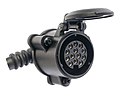
Multicon[1] Feder and Multicon WeSt (Welt Standard) connectors are precursors to ISO 11446 in a design that is intended to be compatible with ISO 1724. This means that if a towing vehicle has an outlet of this type it should be able to connect a trailer with a standard 7-pin or 5-pin connector according to ISO 1724, provided that the trailer coupling follows the standard and that the trailer plug casing is not made of metal since a metal plug will otherwise short the extra pins.
-
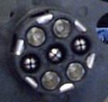 13-pin trailer connection of type Multicon Feder
 -
 13-pin trailer connection of type Multicon WeST


Both connectors have the same electrical wiring[2][3][4] and can be found primarily in the Netherlands and Germany.
| # | DIN | Signal | Colour | Rec. Cross-section | Notes | |
|---|---|---|---|---|---|---|
| mm2 | AWG | |||||
| 1 | L | Left Turn Signal | Yellow | 1.5 | 15 | |
| 2 | 54G | +12V from battery or Rear fog lamps | Blue | 1.5 | 15 | |
| 3 | 31 | Ground connected to chassis | White | 2.5 | 13 | [NEN6120 1] |
| 4 | R | Right Turn Signal | Green | 1.5 | 15 | |
| 5 | 58R | Tail lamps, clearance lamps and registration plate lamp right side | Brown | 1.5 | 15 | [NEN6120 2] |
| 6 | 54 | Stop lamps | Red | 1.5 | 15 | |
| 7 | 58L | Tail lamps, clearance lamps and registration plate lamp left side | Black | 1.5 | 15 | [NEN6120 2] |
| 8 | Reversing lamps, control current to block surge brakes when reversing. | Pink or Red/Black | 1.5 | 15 | ||
| 9 | 30 | +12V permanent | Orange or Brown/White | 2.5 | 13 | |
| 10 | 15 | +12V via ignition lock | Grey | 2.5 | 13 | |
| 11 | Spare | Black/White | 1.5 | 15 | ||
| 12 | Spare until 2012 when it became the trailer detector pin if grounded in the trailer | Light Grey | 1.5 | 15 | ||
| 13 | 31 | Ground (−) for pin 9 and 10 | Red/White | 2.5 | 13 | [NEN6120 1] |
The following supplementary information exists for the connector:
Connectors of DIAB/VBG-typ[edit]
These connectors are specially developed by sv:Djurle Industri AB (DIAB) for severe conditions where snow, ice and salt are common. They can be equipped with an optional heating loop if necessary. Moreover, they are "self-disconnecting" to lower the risk of damage to the connector if the driver should forget to disconnect the plug when disconnecting the trailer or the trailer jumps off the hook.
The 14-pin, 17-pin and 22-pin connectors have the same physical dimensions, but different contact elements in the contacts.
These connectors occur primarily in Scandinavia, but vendors exist in the United States, Belgium and Great Britain, which means that they can be found outside Scandinavia as well.
Connections for these contacts listed as spare are free to use.
Maximum allowable current for ground contact is 25A.
12-pin DIAB P12[6][edit]

This connector is designed for 12V electrical system where the standard ISO connectors are considered insufficient. The connector is designed in the same manner as the connectors for heavy vehicles, but is physically smaller.
| # | DIN | Signal | Colour | Rec. Cross-section | Notes | |
|---|---|---|---|---|---|---|
| mm2 | AWG | |||||
| 1 | 31 | Ground (−) for pin 1–8 | White | 2.5 | 13 | |
| 2 | L | Left Turn Signal | Yellow | 1.5 | 15 | |
| 3 | 54 | Stop lamps | Red | 1.5 | 15 | |
| 4 | 58L | Tail lamps, clearance lamps and registration plate lamp left side | Black | 1.5 | 15 | [DIAB_P12 1] |
| 5 | 58R | Tail lamps, clearance lamps and registration plate lamp right side | Brown | 1.5 | 15 | [DIAB_P12 1] |
| 6 | R | Right Turn Signal | Green | 1.5 | 15 | |
| 7 | Reversing lamps, control current to block surge brakes when reversing. | Pink | 1.5 | 15 | ||
| 8 | Rear fog lamps | Blue | 1.5 | 15 | ||
| 9 | Spare | |||||
| 10 | Spare | |||||
| 11 | Spare | |||||
| 12 | 30 | +12V permanent | Orange | 2.5 | 13 | |
The following supplementary information exists for the connector:
14-pin[7][edit]


| # | DIN | Signal | Colour | Rec. Cross-section | Notes | |
|---|---|---|---|---|---|---|
| mm2 | AWG | |||||
| 1 | 31 | Ground (−) for pin 1–3 and 5–12 | White | 2.5 | 13 | |
| 2 | L | Left Turn Signal | Yellow | 1.5 | 15 | |
| 3 | R | Right Turn Signal | Green | 1.5 | 15 | |
| 4 | 54 | Stop lamps | Red | 1.5 | 15 | |
| 5 | 58L | Tail lamps, clearance lamps, identification lamps and registration plate lamp left side | Black | 1.5 | 15 | [VBG_14 1] |
| 6 | 58R | Tail lamps, clearance lamps, identification lamps and registration plate lamp right side | Brown | 1.5 | 15 | [VBG_14 1] |
| 7A | Reversing lamps | Pink | 1.5 | 15 | ||
| 7B | Rear fog lamps | Blue | 1.5 | 15 | ||
| 8A | Spare | |||||
| 8B | Spare | |||||
| 9 | Spare | |||||
| 10 | Spare | |||||
| 11 | Spare | |||||
| 12 | 30 | +24V permanent | Orange | 2.5 | 13 | |
The following supplementary information exists for the connector:
17-pin[7][edit]


This connector is used in cases where a 14-pin connector is insufficient
| # | DIN | Signal | Colour | Rec. Cross-section | Notes | |
|---|---|---|---|---|---|---|
| mm2 | AWG | |||||
| 1 | 31 | Ground (−) for pin 1–3 and 5–12 | White | 2.5 | 13 | |
| 2 | L | Left Turn Signal | Yellow | 1.5 | 15 | |
| 3 | R | Right Turn Signal | Green | 1.5 | 15 | |
| 4 | 54 | Stop lamps | Red | 1.5 | 15 | |
| 5 | 58L | Tail lamps, clearance lamps, identification lamps and registration plate lamp left side | Black | 1.5 | 15 | [VBG_17 1] |
| 6A | 58R | Tail lamps, clearance lamps, identification lamps and registration plate lamp right side | Brown | 1.5 | 15 | [VBG_17 1] |
| 6B | Spare | |||||
| 7A | Reversing lamps | Pink | 1.5 | 15 | ||
| 7B | Rear fog lamps | Blue | 1.5 | 15 | ||
| 8 | Spare | |||||
| 9A | Spare | |||||
| 9B | Spare | |||||
| 10A | Spare | |||||
| 10B | Spare | |||||
| 11A | Spare | |||||
| 11B | Spare | |||||
| 12 | 30 | +24V permanent | Orange | 2.5 | 13 | |
The following supplementary information exists for the connector:
22-pin[7][edit]

This connector is a further development of the 17-pin connector for cases requiring support for many functions.
| # | DIN | Signal | Colour | Rec. Cross-section | Notes | |
|---|---|---|---|---|---|---|
| mm2 | AWG | |||||
| 1 | 31 | Ground (−) for pin 1–3 and 5–12 | White | 2.5 | 13 | |
| 2A | L | Left Turn Signal | Yellow | 1.5 | 15 | |
| 2B | Spare | |||||
| 3A | R | Right Turn Signal | Green | 1.5 | 15 | |
| 3B | Spare | |||||
| 4A | 54 | Stop lamps | Red | 1.5 | 15 | |
| 4B | Spare | |||||
| 5A | 58L | Tail lamps, clearance lamps, identification lamps and registration plate lamp left side | Black | 1.5 | 15 | [VBG_22 1] |
| 5B | Spare | |||||
| 6A | 58R | Tail lamps, clearance lamps, identification lamps and registration plate lamp right side | Brown | 1.5 | 15 | [VBG_22 1] |
| 6B | Spare | |||||
| 7A | Reversing lamps | Pink | 1.5 | 15 | ||
| 7B | Rear fog lamps | Blue | 1.5 | 15 | ||
| 8A | Spare | |||||
| 8B | Spare | |||||
| 9A | Spare | |||||
| 9B | Spare | |||||
| 10A | Spare | |||||
| 10B | Spare | |||||
| 11A | Spare | |||||
| 11B | Spare | |||||
| 12 | 30 | +24V permanent | Orange | 4–6 | 9–11 | |
The following supplementary information exists for the connector:
See also[edit]
References[edit]
- ^ "Wiring Plan 13 pin Multicon and Multicon We-ST" (PDF). Archived from the original (PDF) on 2013-09-27. Retrieved 2013-09-28.
- ^ "Multicon Feder Manual".[permanent dead link]
- ^ "Multicon WeSt Manual".[permanent dead link]
- ^ "Haynes Trailer Wiring" (PDF).
- ^ a b "HELLA ELECTRICAL PLUG-TYPE CONNECTIONS" (PDF).
- ^ Monteringsanvisning DIAB P12 (in Swedish). Djurle Industri AB.
- ^ a b c "VBG Connector 14 / 17" (PDF).
Symbol Guide[edit]
| Example | Description |
|---|---|
 |
Socket |
 |
Pin |