
Talk:Transformer/Archive 7
| This is an archive of past discussions. Do not edit the contents of this page. If you wish to start a new discussion or revive an old one, please do so on the current talk page. |
| Archive 1 | ← | Archive 5 | Archive 6 | Archive 7 | Archive 8 | Archive 9 | Archive 10 |
Old discussions
Old discussions have been moved to archives - use the navigation box to switch between them. I used the much nicer {{archives}} and {{archivesnav}} templates as found on the Personal computer talk pages to spruce up navigation a little. Rememember when creating new archive pages that they must have a space in the title - talk:transformer/Archive 7 would be the next page, for example. --Wtshymanski (talk) 21:55, 4 September 2009 (UTC)
Plugwash - please look at the transformer equation
From the transformer article:
- and


That is, the rate of change of flux at any instant is proportional to the instantaneous voltage. A non-zero voltage produces a non-zero rate of change of flux. A changing flux does not require a changing voltage. That's precisely what that equation says. Do you disagree? Alfred Centauri 02:59, 5 April 2007 (UTC)
- This is a case where the equations have been simplified so much from reality that they imply a behaviour that can't happen in any real transformer. Since any transformer has both nonzero series resistance and noninfinite paralell inductance any DC voltage applied to the transformer will be dropped entirely over the resistance and will therefore not contribute to the magnetic flux. Therefore all changes in flux are a (possiblly delayed) result of a change in applied voltage.
- Afaict in electronics a common approximation is to consider a transformer as if it were an ideal transformer apart from the fact it blocks DC. Plugwash (talk)
- But if I take a little control transformer and put some DC on the secondary, if I try to take it apart *something* is holding the core in with great effort. There's got to be flux even with DC applied to a practical transformer! --Wtshymanski (talk) 03:09, 4 September 2009 (UTC)
This thread confuses me. Is it in reference to some particular part of the article? I could try to help explain but I'm not sure what question we are trying to answer. Ccrrccrr (talk) 21:47, 4 September 2009 (UTC)
- "But if I take a little control transformer and put some DC on the secondary, if I try to take it apart *something* is holding the core in with great effort. There's got to be flux even with DC applied to a practical transformer!".
- In the steady state with a DC input on a real transformer there is flux but not change in flux. As there is no change in flux there is nothing to induce voltage in the secondry.
- When a step change is applied the initial step will be passed but will then gradually decay away since the real transformer is essentially a bandpass filter (as can be seen from the "equivilent circuit" in the article)
- "This thread confuses me. Is it in reference to some particular part of the article?"
- It was started by alfred when he reverted my edit ( http://en.wikipedia.org/w/index.php?title=Transformer&diff=120396448&oldid=120392870 ). I didn't notice it for some time but when I did I dug up the edit and then tried to explain the situation which is that DC blocking is both useful and a basic physical characterstic of a transformer even though the most simplified equations would seem to indicate an ability to pass DC. Plugwash (talk) 23:04, 6 September 2009 (UTC)
- Thanks! I think the problem is that the issue is a subtle one, and not likely to be fully accurately addressed in the lead. I can't say that either wording is "correct" in the sense that it's fully accurate. I think the solution would be to explain more fully elsewhere in the article, and perhaps add an extra sentence to the lead, saying something along the lines that transformers don't work with dc. Ccrrccrr (talk) 22:58, 9 September 2009 (UTC)
Use of Single phase versus three phase
What is the advantage of using 3-single phase transformer VS 1-three pahse transformer, aside from physical side, I am talking about big power transformers, e.g. 30MVA —Preceding unsigned comment added by 216.135.182.146 (talk) 20:18, 18 September 2008 (UTC)
- Transport weight is lower. Very large 3-phase transformers may exceed transport ratings and height limits. 30MVA is not exceptionally large, by the way. 600MVA 3-phase units are commonly transported. The 800MVA transformers I once worked on were however constructed as three single units. — BillC talk 22:05, 18 September 2008 (UTC)
- Extremely high voltage transformers or the need for high-reliability systems are also candidates for single-phase components. I helped install a 133MVA single-phase transformer in Ft. Smith AR that transformed 500kV to 161kV. It was so large that it was shipped in pieces: the bottom half held the transformer core and windings, the top half that held the primary bushing. The top half was filled with oil after it was installed over the bottom half. The combined unit was too tall to ship. OG&E put a fourth transformer in the substation to back up any one of the other three that might fail. It was hauled by truck from a rail siding (in 1967, only two US companies had the equipment to do it). I believe that transporting a 400kVA 500/161kV transformer of mid-1960s design would have been a major challenge. — Fred4570 talk 1424, 2011-08-20(UTC)
Question about wheels
what is the reason almost all the power transformation installed along with the wheel.why not without wheel. —Preceding unsigned comment added by 196.44.248.134 (talk) 12:31, 30 September 2008 (UTC)
Order of article
This article recently had history moved up and applications moved down. I don't think that's appropriate for a technology article. The most important thing about technology is its application; it's history is often omitted from, for example, a textbook. Other topics are different. For example, in science, the phenomenon would be primary; applications secondary. I'm not aware of WP policy in this regard--I'm just stating my opinion. But I think that a change like that needs discussion. Ccrrccrr (talk) 22:20, 22 November 2008 (UTC)
- Disagree. Engineering textbooks, in particular, shamefully neglect the history of just about everything...everything is handed down as if on a stone tablet, with no indication of the origins except a random name or date. (There's a reason for this...engineering students have limited time and interest, and textbooks can't afford to take the space to go into the history...look at Friedel's and Hughes' books for just how much space it takes to talk about history.) I don't think you can understand the applications of anything until you have some notion of where it came from and why it was created in the first place. --Wtshymanski (talk) 16:32, 23 November 2008 (UTC)
- I agree that someone who wants an in-depth understanding should read the history, and I enthusiastically support having it in here, but I don't think that's the first thing most readers will want to know. Thus, if we follow news style or summary style guidelines it wouldn't come first. But that's just one recommendation, not a firm policy, and there doesn't seem to be much other guidance or policy on order in articles, so let's continue to discuss.Ccrrccrr (talk) 22:24, 23 November 2008 (UTC)
Net flux in transformer core
I notice someone has reverted my correct statement about there being no net flux (apart from magnetising flux) in the core. I would refer the person to any proper textbook on electrical engineering and in particular ,transformers, to establish that I am in fact correct. Also what is LC? Inductor capacitor resonant circuit or something?--GreenSpigot (talk) 01:48, 16 December 2008 (UTC) ~Featured article?
Why isnt this an FA yet (or have I missed it) its certainly inertesting enough and quite stable (apart from the net flux issue)--GreenSpigot (talk) —Preceding undated comment was added at 02:13, 16 December 2008 (UTC).
- You know we all know you, Light current. A lot of work is required to get this article to FA. — BillC talk 02:50, 16 December 2008 (UTC)
Treaths
perhaps a threaths section can be added. Mention the possibility of a Geomagnetic storm —Preceding unsigned comment added by 91.176.221.91 (talk) 09:36, 8 July 2009 (UTC)
History references
For future reference, here's another good article with a lot of detail on how much of an advance the ZBD transformer was:
- "Transformer Invented 75 Years Ago" by Halacsy, A. A. and Von Fuchs, G. H., in Power Apparatus and Systems, Part III. Transactions of the American Institute of Electrical Engineers, April 1961, Volume: 80, Issue: 3 pp. 121-125, ISSN: 0018-9510, Digital Object Identifier: 10.1109/AIEEPAS.1961.4500994
and a book with great detail on the many little advances made in various patents c. 1850 to 1885
- Title The alternate current transformer in theory and practice
- Author John Ambrose Fleming
- Publisher "The Electrician" printing and publishing company, limited, 1892
- Google books link: [1]
-Ccrrccrr (talk) 21:35, 22 July 2009 (UTC)
As all sources state, the most important newness in ZBD was its high efficiency: 98-99 percent(!). The efficiency of Gaulard & Gibbs' former "champion"-system was less than 38 percent.
--Zolika76 (talk) 16:56, 4 September 2009 (UTC)
- This was at least one of Edison's arguments against AC distribution - he knew that a system that was carefully calculated to turn a profit at the efficiencies he could get from DC generators and distribution would be intolerably expensive to run if he had to generatore 2 or 3 times as much power to give the same amount of light. --Wtshymanski (talk) 20:00, 4 September 2009 (UTC)
Needed: article on soft magnetic materials
In editing the lead, I wanted to link to the article on soft magnetic materials. There isn't one! Magnetic material redirects to an article on hard magnetic mateirals (called magnet); soft magnetic material redirects to an article on coercivity.Ccrrccrr (talk) 01:39, 25 July 2009 (UTC)
Invention of Transformer formula
Ottó Bláthy turned his interest more and more towards electro-technology and thoroughly studied Faraday's experiments and Maxwell's theoretical work. He soon recognised a method of practically applying Ohm's magnetic law, the connection between the magnetic field and the excitation creating it. Bláthy was the first who was able to calculate magnetic circuits using magnetising curves and, in this way, economically design electric direct current machines.
http://www.omikk.bme.hu/archivum/angol/htm/blathy_o.htm --Zolika76 (talk) 18:38, 9 September 2009 (UTC)
- The above comment is entirely plagiarized from the source material. It also has little if any relevance to the "Invention of Transformer formula". Moreover, it is almost certainly posted by banned user Celebration1981. Rico402 (talk) 21:31, 9 September 2009 (UTC)
- Not likely he merely got the mechanics wrong. Zolika76 is a sockpuppet of Celebration1981, and plagiarism is his customary method of adding content. (I just rephrased a bit of his plagiarism re the Ganz Company's work.) He's been blocked as of 22:47, 9 September 2009 (UTC). (And I had nothing to do with it. ;) Cheers, Rico402 (talk) 00:37, 10 September 2009 (UTC)
I suggest this whole section be deleted, as it is just more blather from banned user Celebration1981 using sockpuppet Zolika76. Rico402 (talk) 20:15, 17 September 2009 (UTC)
PS: The transformer formula is not an "invention"; Bláthy et al discovered and formalized the relationship between turns ratio and emf. A discovery or realization does not constitute "invention". (Did Einstein "invent" E = mc2 ?) Rico402 (talk) 20:30, 17 September 2009 (UTC)
Title of Faraday section
There seems to be an edit war going on over the title of the section about Faraday. Please discuss here rather than engaging in an edit war. Ccrrccrr (talk) 22:53, 9 September 2009 (UTC)
- Well, one warrior has been banned for now, so at least you might get a civil discussion. I have no strong feelings on the matter, but it seems to me that "Discovery" is too vague a title. "Discovery of induction phenomenon" isn't bad, but perhaps "Discovery of electrical induction" would be more appropriate; or just "Electrical induction" (or "Electrical self-induction", sans the italics).
- Btw, I'm of the opinion that at some point this subsection should be expanded a bit. In particular, I would like to see Joseph Henry mentioned, as he discovered electrical induction independently and at about the same time as Faraday, and of course, the SI unit of inductance (the "henry") is named after him. (Although apparently Faraday formalized the equations.) Cheers, Rico402 (talk) 04:46, 13 September 2009 (UTC)
- Research away, but Henry didn't do much for transformers as such and his contributions should be amplified elsewhere. Hungarian nationalism aside, it's plain that whatever Faraday called his device, it's a transformer - it even has the much-praised closed magnetic core. I don't know if Faraday ever published any description of a theory as to how his device worked or if he ever worked with AC on it. --Wtshymanski (talk) 14:27, 13 September 2009 (UTC)
- I don't disagree that "whatever Faraday called his device, it's a transformer". (Nor that he essentially invented the electric motor as well.) In fact, I would like the article to expand a bit on Faraday's contributions to the development of the transformer. (That's something I was hinting at when I wrote that the "subsection should be expanded a bit.")
- Re Henry: I was just referring to a mention of his co-discovery of electromagnetic induction. For example: "In 1831, Michael Faraday and Joseph Henry, working independently, discovered the phenomenon of electromagnetic induction, [the whatever of the whatever]. Faraday would go on to [blah, blah, and blah], now known as 'Faraday's law of induction', or simply 'Faraday's law'." (I believe this is covered in one of the refs already cited.)
- At present it reads, "Michael Faraday discovered the principle of induction, Faraday's induction law, in 1831 and did the first experiments with induction between coils of wire", suggesting that Faraday alone discovered the principle of electromagnetic induction, which simply isn't true. Nor is it true that "the principle of induction" is "Faraday's law of induction". The law of induction describes and mathematically formalizes the induction phenomenon; it is not the phenomenon itself. So that bit needs some clarification. Cheers, Rico402 (talk) 20:26, 14 September 2009 (UTC)
Naming
Can it be mentioned in the definition that electricity transformer or electrical transformer are also valid terms ? http://encyclopedia.farlex.com/Electrical+transformer Transformer alone can also mean "one who transforms" (eg shapeshifter, ...) ; see http://dictionary.reference.com/browse/transformer —Preceding unsigned comment added by 81.243.187.171 (talk) 15:15, 12 September 2009 (UTC)
- That would be redundant; the header already states "This article is about the electrical device". What you're suggesting is differentiating the term from a non-specific "dictionary definition". Moreover, it's quite common, perhaps more often than not, that names given to electrical/electronic devices (or properties) have a much broader application outside this technological sphere; e.g., a "resistor" is anything (or anybody) that "resists", yet in electronics it refers to a component capable of performing a specific function within a circuit. Such nominal specificity is exceedingly common, which is why we have "disambiguation" pages. Cheers, Rico402 (talk) 04:00, 13 September 2009 (UTC)
Definition change
A transformer is a device that that converts high-voltage electrical energy to low-voltage electrical energy or vice versa. A transformer that converts high-voltage to low-voltage energy is called a step-down transformer. A transformer that converts low-voltage to high-voltage is called a step-up transformer. —Preceding unsigned comment added by 81.245.90.148 (talk) 09:22, 9 October 2009 (UTC)
- True, and the "dictionary definition" suggested by 81.245.90.148 is not only limiting, but inaccurate; cheers to Wtshymanski for restoring the previous version. However, it may not be a bad idea to insert a few lines that describe the most common (is it?) use of a transformer akin to Ccrrccrr's recent edit; i.e.:
- "Although a transformer may serve a variety of functions, perhaps the most common is to manipulate the EMF of an electrical current. A transformer that converts low voltage to high voltage is called a step-up transformer; a transformer that converts high voltage to low voltage is called a step-down transformer."(Insert appropriate ref.)
- I believe that a transformer that does not change the voltage from primary to secondary is called an "isolation transformer." Fred4570 (talk) 1433, 2011-08-20 (UTC)
- 1:1 transformers have a great many applications in electronics. See for instance repeating coil and these filters. Conference matrix#Telephone conference circuits is also interesting but more theoretical than practical. SpinningSpark 21:59, 20 August 2011 (UTC)
Why?
Why in all languages it is 'transformator' and only in English 'transformer'?--MathFacts (talk) 08:19, 15 December 2009 (UTC)
- Don't really know, but it's probably because a lot of Latin-derived words get shortened in English. Modern English "transform" is derived from Middle English "transformen", from Latin "transformare". (The American Heritage Dictionary, Second College Edition, 1985) It's also common in English to make a noun from a verb by simply adding "er"; maybe in other languages it's done by adding "ator". English is a relatively new and economical language, "borrowing" from many sources, and often simplifying the spelling and pronunciation. Cheers, Rico402 (talk) 08:46, 18 December 2009 (UTC)
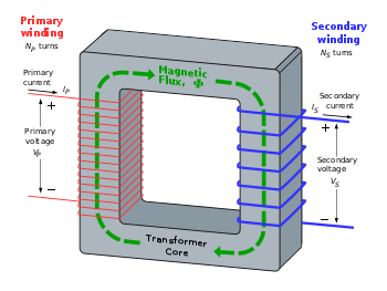
Incorrect image
The first image under the section "Practical Considerations" (located at http://en.wikipedia.org/wiki/File:Transformer_flux.gif) is incorrect. For the shown winding sense, the output (secondary) current would be opposite of what is shown. The first image under "Basic Principles" (located at http://upload.wikimedia.org/wikipedia/commons/thumb/6/64/Transformer3d_col3.svg/350px-Transformer3d_col3.svg.png) is correct, and can/should be used as a reference to fix the image.
For the incorrect image, if the winding sense (and nothing else) is changed, then everything would be correct including voltage, current, and flux orientations (note that the primary leakage flux and mutual flux are in the same direction, but the secondary leakage flux and mutual flux are opposite... This is correct).
I would be happy to provide a correct image if needed.
Cheers, Electrophysics_matt Electrophysics matt (talk) 06:18, 31 December 2009 (UTC)
- I think you should just go ahead and fix it if you can provide a correct image. The different directions is confusing and should be fixed as soon as possible. I don't know how to fix and upload the image though, so I can't really help you there. 218.186.9.246 (talk) 09:55, 23 August 2010 (UTC)
secondary winding, secondary coil, secondary circuit
Was cleaning this DAB page for "Secondary" and came here to see which secondary it was referring to. Very unclear. Are secondary winding, secondary coil, and secondary circuit all the same thing? If so the terminology needs to be cleaned up. Fountains of Bryn Mawr (talk) 23:24, 4 February 2010 (UTC)
- With respect to transformers, "secondary" should only apply to a "secondary winding". (A transformer may have multiple secondaries.) The term is synonymous with "secondary coil", but I believe "winding" is preferred (at least by me ;). The circuit connected to a transformer's secondary is often called a "secondary circuit", and therein lies the confusion.
- The disambiguation page has been edited to (hopefully) clear up the confusion. Cheers, Rico402 (talk) 08:26, 10 February 2010 (UTC)
- Ty for the clearification. I rewrote the DAB entry to match MOS. There is still the small problem of terminology, this article uses the term secondary coil 11 times and secondary winding 18 times with no explanation as to if this is the same thing. Fountains of Bryn Mawr (talk) 14:58, 17 February 2010 (UTC)
Ground loops
In physics experiments 1:1 transformers are often used to eliminate ground loops. I guess it's a similar usage in audio applications. Is it worth mentioning this usage and/or discussing/linking? Grj23 (talk) 05:58, 10 February 2010 (UTC)
- These are isolation and/or impedance matching transformers. Audio signal coupling is mentioned in the intro and there is a brief mention of "isolation" under "Classification", but I suppose the topic could be expanded upon and links added. Audio transformers include 1:1 isolation transformers as well as impedance matching transformers, i.e. a direct box (or DI, for "direct input" or "direct injection") for matching a high impedance output (guitar or keyboard) to the low impedance input of a mixing console. Cheers, Rico402 (talk) 09:07, 10 February 2010 (UTC)
- I use 1:1 transformers all the time in my live sound career. They eliminate ground loops, certainly, and they balance unbalanced circuits such as laptop headphone outputs, or RCA jack outputs, for the purpose of having a very long cable run carry the audio signal to an audio mixer input. I'll keep tabs on any expansion to see if the subject is well treated. Binksternet (talk) 09:31, 10 February 2010 (UTC)
- This article also needs to have ground loop isolation listed: Transformer_types#Audio_transformers.
- Furthermore, the transformer's limited frequency response has been used to help prevent radio frequency interference from causing trouble in an audio mixer. The AM radio band starts around 500 kHz, and 1:1 audio frequency transformers drop sharply in response above some target high frequency design goal such as 20 kHz or whatever, meaning you don't get the local AM station playing in your audio circuit if there is a transformer in line. Audio transformers are limited in their high and low frequency response by several factors, primarily size: high frequency becomes more difficult to obtain with larger transformers, and low frequency becomes more difficult with small transformers.
- HTH. Binksternet (talk) 10:06, 10 February 2010 (UTC)
Split-Phase transformer
Please, when a pole mounted transformer is powered by a single phase primary (typically 7,2 KVAC) and its output is a secondary winding of 240 VAC which is center tapped to produce two 120 VAC sources, it is called split-phase. The secondary center tap is grounded to earth. Please read the Wikipedia http://en.wikipedia.org/wiki/Split_phase article. We should use split-phase when we talk about these transformers and not call them single phase transformers.
Often three single-phase transformer's are powered by three phase electric, typically at 7.2 KVAC. These transformer's secondaries are connected together to power a facility with three phase power.
Sponsion (talk) 13:48, 12 July 2010 (UTC)
- Image caption fixed. Although the center-tap which feeds the neutral conductor is commonly grounded, that is not always the case. Cheers, Rico402 (talk) 11:58, 14 July 2010 (UTC)
Turns Ratio not standardized
Turns ratio is referenced in impedance matching and in the Ideal power equation section of this article. When attempting to document this term, I found conflicting (i.e. reciprocal) definitions, even between prominent manufacturers: [2] and [3]. If the industry doesn't have a widely used standard, I think Wikipedia is not the place to declare one. Comments? I'm still checking on the Np:Ns notation. Overjive (talk) 16:39, 30 December 2010 (UTC)
- I think it's about time somebody wrote the Turns ratio article. It is a confused and confusing subject, with conflicting information given by different authors. Here are some more references in case you would like to do the honors of writing the article:
- "Audio Transformers" by Bill Whitlock of Jensen, a chapter of the timeless classic Handbook for Sound Engineers edited by Glen Ballou. "In this example, a transformer with a 1:2 turns ratio exhibits an impedance ratio of 1:4..."
- "Unwinding Distribution Transformers" by Rane Professional Audio Products, part of RaneNotes
- Simplified Design of Switching Power Supplies by John D. Lenk. "Turns ratio = impedance ratio" (This is only true for 1:1 ratio)
- "The change in impedance is proportional to the square of the turns ratio. For example, if the turns ratio of a transformer is 10:1, the change in impedance is a factor of 100. However, a transformer has no intrinsic impedance of its own"... Scott R. Wilkinson and Steve Oppenheimer in Anatomy of a home studio
- Understanding audio by Daniel M. Thompson
- Foundations of electronics, circuits and devices by Russell L. Meade, Robert Diffenderfer
- "Observe that, although the turns ratio is 5:1, the impedance ratio is 25:1. Thus, the impedance ratio is the square of the turns ratio"... Rufus P. Turner and Stan Gibilisco in Principles and practice of impedance
- Et cetera, et cetera. Good luck! Binksternet (talk) 20:07, 30 December 2010 (UTC)
Well, I described turns ratio in the article, including the ambiguity. An example of an inverted turns ratio is in impedance matching. It is consistent with Binksternet's list above (thanks!) because the impedance ratio is inverted also, i.e. the primary and secondary are swapped for both. Fortunately, the Np:Ns notation was consistent in the ~75 places I checked except for Turner... and Meade... again from Binksternet's list. Overjive (talk) 00:01, 31 December 2010 (UTC)
- Lenk does not write what I said he wrote... Sorry! I picked the incorrect quote up from a Google search which returned maths without the formulae, showing only part of the book. Lenk gets it right inside the book where it matters. Binksternet (talk) 00:05, 31 December 2010 (UTC)
Transformer types
Now that there is a separate Transformer types article, I think the Transformer#Types section in this article can be pared down to a paragraph or two. I have not done this because there appears to be valuable information and reference in this section that do no yet appear in Transformer types or some of the more specific transformer articles. I have moved such content for Autotransformer. I encourage others to pitch in and help with the other types. --Kvng (talk) 17:53, 12 February 2011 (UTC)
Superconducting transformers
Let's not over-sell the efficiency advantage. Large power transformers such as those used for substations are well over 99% efficient. Superconductivity only addresses the copper losses and doesn't touch core loss. I've never seen anyone write about how to design a superconducting power transformer to optimize cost and losses. Superconducting transformers are still experimental. Here's a paper Google found [4] which is fairly recent and still clearly about experimental devices, not something one could get a price quote on; that author says maybe a 0.5% improvement in efficiency, not 1.8% as someone would have expected from the numbers now deleted.The geometry is unfavorable; the core must be at ambient temperature, and only the windings are cooled, so the cryostat is a donut-shape with more surface than one would like. You can't put the iron core in the liquid helium because of its huge heating losses, and you can't do without an iron core because you'd need too much conductor to make an "air core" power transformer. It would be interesting to see a utility assessment of the value of a 0.5% saving on energy dissipated vs. the estimated reliability and probability of loss of the transformer and load - there are no reliability statistics yet. --Wtshymanski (talk) 14:32, 23 February 2011 (UTC)
Citation style
This article does not use any consistent style for citations. The article history is of little help in deciding which style to use; the first references were added by BillC in 2005 using the {{Book reference}} template which is now deprecated and redirects to {{Cite book}}. The two templates appear similar, judging by the discussion at Template talk:Book reference (be sure to not follow the redirect).
So my question is, what citation style should we use for this article? Shall we use the {{Cite xxx}} family since the first reference used a predecessor of that family? Since this article tends to use the same sources over and over, shall we use some form of shortened footnotes?Jc3s5h (talk) 14:01, 3 April 2011 (UTC)
- I say, if you're up for doing the work of smoothing it all out, you can use whatever style you are most comfortable with. --Kvng (talk) 03:11, 4 April 2011 (UTC)
Universal EMF Equation peak flux or flux swing
I have been plagued for years by the question of whether the flux in the universal EMF equation is the peak flux or the flux swing. The flux swing should be twice the peak flux density because the flux can peak during both positive and negative half-cycles and so the volt-seconds applied during a given half-cycle can drive the flux from one peak, through zero, to the opposite peak. Obviously a question of over-thinking a simple design rule.
After spending half the day deriving the equation over and over, I have come to the conclusion that the constant 4.44 or 4 in the equations includes a factor of 2 to convert peak flux density to flux swing.
I was tempted to edit the article to add a note to this effect to help other people with the same confusion. But I'm afraid I may still not have it right. Can someone please verify my statement above before I ruin an otherwise very helpful article?
I found the half-cycle formula to be a bit misleading because I pictured an isolated half cycle and this made me think the factor of 2 was not present. In an isolated half-cycle, the flux would not be starting at the opposite peak so you can't use the whole flux swing, just half of it.
Thus, I would argue that either the description of the half cycle version needs to be changed or the formula should be:
Vavg = 2 f N a Bpk
With the constant 4 in it, this formula is only valid if the half cycle in question is part of a continuous, symmetrical, periodic signal. You might say this is always the case, but it's not true of many applications of pulse transformers or in most forward converters.
Even in plain-old line-frequency power transformers, if designed with the "4" version, the first half cycle can saturate the core. You can actually hear this sometimes, especially in toroids.
Mark.sullivan (talk) 23:29, 17 April 2011 (UTC)
- The equation with 4.44 holds ONLY for sinusoidal voltage/flux. The simplified equation is Vrms=4.44*f*B*N*A, which is simply Vrms=sqrt(2)*pi*f*B*N*A, hence this is equivalent to the peak voltage Vpeak=2*pi*f*B*N*A - where the Vpeak means zero-to-peak value, and B means zero-to-peak flux. So the flux swing is therefore 2*B. Using maths it can be proven that without even harmonics (i.e. even for non-sinusoidal waveforms) the equation is true as Vav=4*f*B*N*A. It is very easy to see why it is that way - for sine the rms value is sqrt(2), but the average is 2/pi and the results from that. --Zureks (talk) 09:12, 18 April 2011 (UTC)
Another Incorrect image
[This image] is incorrect, the current on the right should be going from top to bottom, rather than bottom to top with the winding arrangement shown. I've applied to [the illustration lab] to get it fixed. Larryisgood (talk) 12:11, 16 August 2011 (UTC)
- No it isn't. Application of the RH twist rule gives correct direction of flux for both windings. This is a featured picture and likely to have been checked by many thousands of people. SpinningSpark 13:11, 16 August 2011 (UTC)
- I believe it was wrong but is now correct. The fact that it is "likely to have been checked by many thousands of people" does not persuade me. Larryisgood (talk) 15:42, 16 August 2011 (UTC)
- Oh yes, never expected it to be fixed that quick so did not look for an older version (the old transformer page, of course, will also now have the new version as well). I agree now, the old version is incorrect. SpinningSpark 16:28, 16 August 2011 (UTC)
- Regarding the secondary current: Is it the current that arrises in a load as a result of the secondary EMF or is it a current sourced from an independent source?Constant314 (talk) 19:10, 16 August 2011 (UTC)
The latter.The former. The primary coil induces magnetic flux in the core, and this flux induces an EMF in the secondary coil. Larryisgood (talk) 20:09, 16 August 2011 (UTC)- I think you mean "the former", namely "the current that arrises in a load as a result of the secondary EMF" Overjive (talk) 20:58, 16 August 2011 (UTC)
- I contorted my right hand around the primary and secondary. It apears that the secondary current, as drawn, adds to the flux created by the primary current and thus increases the energy stored. So it must be caused an external source, I think.Constant314 (talk) 05:33, 17 August 2011 (UTC)
- I think you mean "the former", namely "the current that arrises in a load as a result of the secondary EMF" Overjive (talk) 20:58, 16 August 2011 (UTC)
- Regarding the secondary current: Is it the current that arrises in a load as a result of the secondary EMF or is it a current sourced from an independent source?Constant314 (talk) 19:10, 16 August 2011 (UTC)
- Oh yes, never expected it to be fixed that quick so did not look for an older version (the old transformer page, of course, will also now have the new version as well). I agree now, the old version is incorrect. SpinningSpark 16:28, 16 August 2011 (UTC)
- I believe it was wrong but is now correct. The fact that it is "likely to have been checked by many thousands of people" does not persuade me. Larryisgood (talk) 15:42, 16 August 2011 (UTC)
I can only imagine the hours that electronic engineering freshmen have argued about this diagram. I think you'll find plugwash, that if you were to reverse the winding on the right hand side (rather than mirroring the left hand side as it does now), that the voltage would indeed be the opposite way around. But with the winding as it is, i believe the image is correct now. Before other people ask whether or not this image is correct, i would ask them to use the [corkscrew rule] to see that the flux through the wire coils produced the direction of current shown.Larryisgood (talk) 09:55, 17 August 2011 (UTC)
- I think that if the secondary current was load current then it should be drawn coming out of the positive terminal.Constant314 (talk) 14:39, 17 August 2011 (UTC)
- The image shows the secondary current exiting the positive terminal until I descend into the linked diagram. Which version is the corrected one? Overjive (talk) 16:07, 17 August 2011 (UTC)
- All I see is a diagram with the current going into the positive terminal.Constant314 (talk) 16:20, 17 August 2011 (UTC)
- Clear your browser cache, then look again at the image. Or open it in a different browser you haven't used before to view the image. The image right now, as it is presented to a browser is correct. If you are still seeing the erroneous diagram it is because you are viewing a cached version on your hard drive.Larryisgood (talk) 18:00, 17 August 2011 (UTC)
- All I see is a diagram with the current going into the positive terminal.Constant314 (talk) 16:20, 17 August 2011 (UTC)
- The image shows the secondary current exiting the positive terminal until I descend into the linked diagram. Which version is the corrected one? Overjive (talk) 16:07, 17 August 2011 (UTC)
- I think that if the secondary current was load current then it should be drawn coming out of the positive terminal.Constant314 (talk) 14:39, 17 August 2011 (UTC)
- So, am I supposed to see current going into or out of the positive terminal? Constant314 (talk) 01:21, 18 August 2011 (UTC)
- The proposed mod (shown in the diagram) is to have current flowing into the positive terminal of the secondary Overjive (talk) 01:48, 18 August 2011 (UTC)
- good, that is what I see. That would be the classic two-port convention. So, it is drawn as if there is a source driving each winding. If the secondary current is actually load current then its value would be negative relative to the primary. Constant314 (talk) 02:39, 18 August 2011 (UTC)
- The proposed mod (shown in the diagram) is to have current flowing into the positive terminal of the secondary Overjive (talk) 01:48, 18 August 2011 (UTC)
- So, am I supposed to see current going into or out of the positive terminal? Constant314 (talk) 01:21, 18 August 2011 (UTC)
I reverted the change to the image. As Constant314 points out, if the current is measured in the direction of that swapped arrow, the secondary current would be negative relative to the primary current. Surely this is not what was intended, which was that the arrows would indicate that if current goes in this way, it comes out this way. The right-hand rule doesn't apply on the secondary side, because the flux is not caused by the secondary current; on the contrary, the secondary current causes a flux in the opposite direction. What's wrong or misleading about the image, if anything, is the flux arrow, not the current arrow. That is, assuming that is it intended to show energy transfer from primary to secondary, which I think is what those terms imply. Maybe it needs to be clarified, but until it is, let's leave it in the state that matches what is likely to be the more common interpretation. Dicklyon (talk) 04:40, 18 August 2011 (UTC) I just read the explanation with the image; it is correct, but doesn't have a current flowing in the secondary, so the flux arrow is also correct (more or less). The voltage direction is correct, and if you connect a load, it will draw a current from the secondary in the direction shown, which is the direction that will tend to decrease the flux. This is all good. Dicklyon (talk) 04:49, 18 August 2011 (UTC)
- I agree with reverting the diagram to show the secondary current exiting the positive terminal. Transformers do not operate at DC, but they only have a small AC phase lag in my experience. Reverting the arrow will show the primary-to-secondary polarities, for both current and voltage, in the transformer's most common application (primary driven and a resistive secondary load, again in my experience). This is the direction of the arrows in citations 33 and 35, and in the 7th external link, and there are no arrows in the opposite direction (except citation 3 which has both primary and secondary driven). Overjive (talk) 05:14, 18 August 2011 (UTC)
- I also edited the article to clarify what the secondary current arrow means; it's a bit awkward, so if someone can phrase it better, please do. Dicklyon (talk) 06:24, 18 August 2011 (UTC)
- So then we should revert [this] image? As you can see, the windings on the right hand (seocndary) side are coiled in the opposite way to the diagram we were previosuly discussing. So if you are correct, at least one of the diagrams is wrong. Larryisgood (talk) 13:45, 18 August 2011 (UTC)
- Yes, as I understand it, that drawing needs to have the secondary current reversed. Using Lenz law helps you determine the direction. If the primary current causes the flux to increase, the resulting secondary current should oppose the change; the secondary current should be in a direction that diminishes the flux. Constant314 (talk) 13:53, 18 August 2011 (UTC)
- Yes, in the section above about that image, I left a note that it's still wrong; I didn't see that it had been changed (maybe I failed when comparing the versions?). It's a bit more complicated, with the different flux arrows; at least the secondary leakage flux and current should be mutually consistent; the secondary current might be drawn either way, depending on how it is described and interpreted. Dicklyon (talk) 20:03, 18 August 2011 (UTC)
- It would be more clear if the secondary arrow exited the positive terminal, even if we had to reverse the windings in the drawing. This would indicate that the signals into the primary and out of the secondary are roughly in-phase, and would agree with our references. Overjive (talk) 20:47, 18 August 2011 (UTC)
- The drawing looks correct to me. The secondary current arrow exits the positive terminal, and if I align my right thumb with the secondary current, it opposes the magnetic field created by the primary. Am I missing something? Overjive (talk) 20:59, 18 August 2011 (UTC)
- I think you are talking about the picture in the Basic Priciples section. We are now talking about the picture in the Leakage flux section. It does not have a terminal labeled with polarity. Constant314 (talk) 21:54, 18 August 2011 (UTC)
- The drawing looks correct to me. The secondary current arrow exits the positive terminal, and if I align my right thumb with the secondary current, it opposes the magnetic field created by the primary. Am I missing something? Overjive (talk) 20:59, 18 August 2011 (UTC)
- It would be more clear if the secondary arrow exited the positive terminal, even if we had to reverse the windings in the drawing. This would indicate that the signals into the primary and out of the secondary are roughly in-phase, and would agree with our references. Overjive (talk) 20:47, 18 August 2011 (UTC)
- Yes, in the section above about that image, I left a note that it's still wrong; I didn't see that it had been changed (maybe I failed when comparing the versions?). It's a bit more complicated, with the different flux arrows; at least the secondary leakage flux and current should be mutually consistent; the secondary current might be drawn either way, depending on how it is described and interpreted. Dicklyon (talk) 20:03, 18 August 2011 (UTC)
- Yes, as I understand it, that drawing needs to have the secondary current reversed. Using Lenz law helps you determine the direction. If the primary current causes the flux to increase, the resulting secondary current should oppose the change; the secondary current should be in a direction that diminishes the flux. Constant314 (talk) 13:53, 18 August 2011 (UTC)
- So then we should revert [this] image? As you can see, the windings on the right hand (seocndary) side are coiled in the opposite way to the diagram we were previosuly discussing. So if you are correct, at least one of the diagrams is wrong. Larryisgood (talk) 13:45, 18 August 2011 (UTC)
- I also edited the article to clarify what the secondary current arrow means; it's a bit awkward, so if someone can phrase it better, please do. Dicklyon (talk) 06:24, 18 August 2011 (UTC)
- The only way I know to fix a drawing is to replace it entirely. I suppose that it could have a caption added that says that the secondary current direction is backward. Constant314 (talk) 04:35, 19 August 2011 (UTC)
- If you go to my talk page you can see my quick mod to the drawing. Larryisgood knows how to get real graphics guys to do it. How about I pursue this? Overjive (talk) 06:12, 19 August 2011 (UTC)
- If you're logged in at commons, the image page will show a link "upload a new version of this file". So you download it, edit it, and upload the new version. Or ask the original contributor if he's interested in fixing it. Dicklyon (talk) 06:13, 19 August 2011 (UTC)
- I described it as a "Preliminary mod of Transformer_flux.gif - for demonstration purposes". I'm new to Wikipedia's drawing upload. Is there another way to share graphic info that's not ready for prime time? Overjive (talk) 06:42, 19 August 2011 (UTC)
- Sorry, I'm not really sure about sharing rough drafts; just upload improvements. I don't see why you need to share a half-way attempt to fixing it. And I don't see why you reversed one of the flux arrows in the secondary leakage flux loop. Dicklyon (talk) 06:51, 19 August 2011 (UTC)
- I modified the flux leakage drawing so the secondary winding is reversed, consistent with the rest of the article. I'll delete my "demo version" of the drawing as soon as I figure out how. Overjive (talk) 08:25, 19 August 2011 (UTC)
- Looks like you got it right. How did you modify it? Constant314 (talk) 13:42, 19 August 2011 (UTC)
- Microsoft Paint did it! The Windows 7 version allows you to select a rectangle, and under "rotate" you can then flip the selected area. I just flipped the whole secondary vertically. Later, I did two more flips to fix the arrows which had been reversed by the first flip. Overjive (talk) 15:47, 19 August 2011 (UTC)
- Looks like you got it right. How did you modify it? Constant314 (talk) 13:42, 19 August 2011 (UTC)
- I modified the flux leakage drawing so the secondary winding is reversed, consistent with the rest of the article. I'll delete my "demo version" of the drawing as soon as I figure out how. Overjive (talk) 08:25, 19 August 2011 (UTC)
- Sorry, I'm not really sure about sharing rough drafts; just upload improvements. I don't see why you need to share a half-way attempt to fixing it. And I don't see why you reversed one of the flux arrows in the secondary leakage flux loop. Dicklyon (talk) 06:51, 19 August 2011 (UTC)
- I described it as a "Preliminary mod of Transformer_flux.gif - for demonstration purposes". I'm new to Wikipedia's drawing upload. Is there another way to share graphic info that's not ready for prime time? Overjive (talk) 06:42, 19 August 2011 (UTC)
- The only way I know to fix a drawing is to replace it entirely. I suppose that it could have a caption added that says that the secondary current direction is backward. Constant314 (talk) 04:35, 19 August 2011 (UTC)
Main or mains?
The article says "Powdered iron cores are used in circuits such as switch-mode power supplies that operate above main frequencies and up to a few tens of kilohertz".
Should it be "mains"?
ICE77 (talk) 05:25, 26 December 2011 (UTC)
- Yes it should; it's been corrected. Cheers for spotting the typo. Best, Rico402 (talk) 09:28, 26 December 2011 (UTC)
Interesting claim
The article currently claims:
"A steel core's remanence means that it retains a static magnetic field when power is removed. When power is then reapplied, the residual field will cause a high inrush current until the effect of the remaining magnetism is reduced, usually after a few cycles of the applied alternating current." followed by a cite.
Unfortunately, I can't find a copy of the book to check the reference, but unfortunately remnant magnetism has nothing whatsoever to do with inrush current. I can only assume that someone has misinterpreted what the refered work says (as I can't believe they got it wrong). In any case, what is the mechanism whereby, this remnant magnetism is reduced? An alternating field won't do it, unless it is gradually reduced to zero (or saturates the core at both extremes - undesireable in a transformer). Inrush current is affected by many factors but in any particuar transformer, there is zero inrush current if the supply is switched on at any moment that the instantaneous voltage is zero (regardless of any remnant magnetism).
If the supply is switched on at any moment the instantaneous voltage is at a maximum (either positive or negative), the inrush current is at its maximum. Inrush current varies between zero and this maximum depending on exactly which point of the cycle the supply is switched. The magnitude and duration of the inrush current can be calculated using some complicated mathematical stuff, which will involves the solution of a differential equation (and I have done a fair few of these in my time).
There has been much effort expended in producing systems that switch the supply at a zero crossing point and thus enable the circuit protection to be much tighter than would otherwise be the case.
Since the article claim is cited, I an loath to change it, unless I can dispute the original citation (though I do have citations for my version - but they are probably equal in weight). DieSwartzPunkt (talk) 13:59, 7 February 2012 (UTC)
- Hitting "Google Books" with "transformer inrush remanence" gives about 200 hits, many of which look relevant. The IEEE should be informed of this error at once, as they apparently continue to believe that remanance has some influence on transformer inrush. They may also have to be educated away from preaching this imaginary unidirectional offset "DC" componenent that exponentially decays over several seconds, thereby eliminating the remanent flux. In the general case, at least two legs of a 3-phase transformer will have non-zero switching voltages and there's no way to guarantee that the remanent magnetism in the core matches the instantaneous voltage at the moment of switching.
- If I had a dollar for every time I've heard a 30 MVA transformer hit with 13.8 kV go "BUZZZZZZZzzzzzzzz", I'd have retired long ago. I also had the misfortune of being flown to an isolated community to figure out why the 66 kV line protection was tripping every time a new transformer was switched on. --Wtshymanski (talk) 17:44, 7 February 2012 (UTC)
- Well I also hear transformers go BZZZzzz, though with single phase, not every time you switch 'em on. I was taught all about the inrush current as a student (prediction of it was called transient analysis at the time - and probably still is), and did the calculations to predict size and duration on many occasions since (and hence determine what size hack-saw blade to put in the fuse box!). And being a lazy sod, I solved the resulting diff equations using laplace transforms and partial fractions which was infinitely easier than doing it the proper way*. Zero crossing switching systems always virtually eliminated the transient at switch on (and any left over was usually inaccuracies in the switch point). However, this technique was difficult to apply to large high voltage transformers and certainly to three phase transformers (though, thinking about it, I reckon it could be done for 3 phase). I still have my student text book, and it has a whole chapter on the subject including the maffs (though doesn't mention laplace).
- * These days, my pocket calculator would do the job at the touch of a button (well, several buttons actually) if I still did that sort of thing. DieSwartzPunkt (talk) 18:26, 7 February 2012 (UTC)
- My memory of the explanation is that if the transformer has zero remanence when power is connected, then the transformer looks like an inductor and the inductance limits the inrush current. If the transformer is left with a very high remanence and power is connected it could be that the incoming current adds to the remanence and quickly saturates the core. Then the inductance is greatly reduced and the inrush current is much larger. It doesn’t happen every time. A random turnoff relative to phase and a random turn on relative to phase only creates a worst case event occasionally. Constant314 (talk) 21:22, 7 February 2012 (UTC)
- Ah, magnetic theory: it was a very long time ago wasn't it? Your theory, is faulty. Application of a magnetising force (B) produces a flux (H) in the core. Removal of that force leaves a residual magnetic flux in the core (remanance). If the magnetising force is once again applied gradually, the force must substantially approach the magnitude that would have been responsible for the magnitude of the remanant flux before any increase in flux ensues (exact behaviour is, of course, dependant on the core material). Thus when the magnetising force reaches its full value, the flux will be exactly the same rgardless of whether any remanent flux was present or not - provided the final flux does exceed the remanent. In a soft iron cored transformer, the remanence is never going to be particularly large.
- If the core did saturate in a transformer, it would not be a very good transformer as the instantaneous current would rise very sharply as the core saturated (as it's magnetic properties would be substantially reduced, if not totally eliminated once the change in flux was reduced (all, once again, dependant on core material)). This would provide a considerable power wastage. Transformers are operated on as near a linear part of the B-H curve as possible. 109.145.21.107 (talk) 13:34, 15 February 2012 (UTC)
- Depends on the size of transformer. It's not a very economical use of core steel if you insist on running at low flux. Large power transformers are usually operated pretty close to the "knee" of the curve; you might find in a specification language something like "increasing the voltage by 5% over nominal shall not increase the magnetizing current by more than 20%" or numbers like that. --Wtshymanski (talk) 19:09, 15 February 2012 (UTC)
- If the core did saturate in a transformer, it would not be a very good transformer as the instantaneous current would rise very sharply as the core saturated (as it's magnetic properties would be substantially reduced, if not totally eliminated once the change in flux was reduced (all, once again, dependant on core material)). This would provide a considerable power wastage. Transformers are operated on as near a linear part of the B-H curve as possible. 109.145.21.107 (talk) 13:34, 15 February 2012 (UTC)
- Most transformer core material has a relatively long and thin B-H curve (compared to harder materials) which is fairly linear almost up to the 'knee'. 109.145.21.107 (talk) 12:52, 16 February 2012 (UTC)
- I think I know what you are trying to say, but "fairly linear" just doesn't have a precise meaning. Some numbers would be more informative.Constant314 (talk) 00:20, 17 February 2012 (UTC)
Core form and shell form vs. shell-core
Discussion open - Collapsed for convenience
| |||||
|---|---|---|---|---|---|
|
Cblambert (talk) 02:59, 16 February 2012 (UTC)Article mistakenly refers to 'shell-core' instead of distinguishing between two fundamental transformer constructions, shell form and core form. In shell form construction corresponding L&HV windings are on the same core whereas in core form construction corresponding L&HV windings are on separate cores. See Fig. 4 of 'The transformer [historical overview]' by Coltman, J.W. which appeared in IEEE's Industry Applications Magazine on Jan/Feb 2002. Cblambert (talk) 05:33, 16 February 2012 (UTC) See also Fig 18 from Professor Lucas's 'Historical Development of the Transformer', as it seems to differ from Coltman's description.
Cblambert (talk) 22:18, 24 February 2012 (UTC)
I think I have the originals still, so I can make modifications if you wish. Constant314 (talk) 02:37, 28 February 2012 (UTC)
Talk-Specific References
|
Bibliography of transformer books
Discussion closed - Collapsed for convenience
|
|---|
| Cblambert (talk) 04:26, 2 March 2012 (UTC)
I suggest adding the following external link:
|
Leakage transformer
Discussion open - Collapsed for convenience
|
|---|
|
Not to put too fine a point on it, but I can't help be puzzled at 'Leakage transformer' being showcased among handful of transformer types in Types section. Of 3,134,656 documents in the IEEE Xplore digital database, I can only find:
Also, while numerous excellent references old and new exist for welding transformer and power supplies, I can't find that would explain 'leakage transformer' applied to welding. The word 'leakage' has inherent negative connotations. 'Leakage transformer' is technically accurate in lighting ballast application but is evidently off the heavily travelled engineering path, never mind the lay user path . . .BTW, excellent article.Cblambert (talk) 05:45, 18 February 2012 (UTC)
|
Electronics Components
Discussion closed - Collapsed for convenience
|
|---|
| Cblambert (talk) 04:32, 2 March 2012 (UTC)
There is a disconnect between whole 'Transformer' article and inclusion of 'Electronics Components' template. No? Would not 'Power Delivery' template be better?Cblambert (talk) 22:37, 18 February 2012 (UTC)
|
Types
Discussion open - Collapsed for convenieunce
|
|---|
| Cblambert (talk) 04:36, 2 March 2012 (UTC)
Article's 'Types' section could be more rigorous, generic and consistent in its treatment. For example, whereas Polyphase transformer type suggests all the other transformer types might not be polyphase, autotransfomer/leakage/resonant transformer types are sometimes polyphase, sometimes single-phase; also some polyphase transformers are two-, three-, six-phase, and so on but not always three-phase. A zigzag transformer ia not so much a polyphase transformer example, a polyphase transformer normally being used in power or distribution applications (see The Basics of Zigzag Transformers), as it is way of creating an artificial neutral (very often but not always also connected to the secondary of a wye-delta double-wound three-phase transformer) for grounding purposes. Regarding autotransformer type, it is far from clear that some of the largest rating, extra high voltage transformers are autotransformers; also some high reactance autotransfomer lighting ballasts could evidently be considered to be of the 'leakage transformer' type (see GE HID Ballast Application Guide).Cblambert (talk) 18:34, 21 February 2012 (UTC)
|
Discussion closed - Collapsed for convenience
|
|---|
| Cblambert (talk) 04:45, 2 March 2012 (UTC)
Was former section Closed-core transformer and introduction of parallel connection - DRAFT   In the autumn of 1884, Károly Zipernowsky, Ottó Bláthy and Miksa Déri (Z.B.D.), three engineers associated with the Ganz factory, had determined that open-core devices were impracticable, as they were incapable of reliably regulating voltage.[3] In their joint 1885 patent applications for novel transformers (later called Z.B.D. transformers), they described two designs with closed magnetic circuits where copper windings were either a) wound around iron wire ring core or b) surrounded by iron wire core.[1] The two designs were the first application of the two basic transformer construction types in common use to this day which can as a class all be termed as either core-form or shell-form (or alternatively, core-type or shell-type), as in a) or b), respectively (see images).[4][5][6][7] The Ganz factory had also in the autumn of 1884 made delivery of the world's first five high-efficiency AC transformers, the first of these units having been shipped on September 16, 1884.[8] This first unit had been manufactured to the following specifications: 1,400 W, 40 Hz, 120:72 V, 11.6:19.4 A, ratio 1.67:1, one-phase, shell-form.[8] In both designs, the magnetic flux linking the primary and secondary windings traveled almost entirely within the confines of the iron core, with no intentional path through air (see 'Toroidal cores' below). The new transformers were 3.4 times more efficient than the open core bipolar devices of Gaulard and Gibbs.[9] Their patents included two other major interrelated innovations: one concerning the use of parallel connected, instead of series connected, utilization loads, the other concerning the ability to have high turns ratio transformers such that the supply network voltage could be much higher (initially 1,400 to 2,000 V) than the voltage of utilization loads (100 V initially preferred). [10][11] When they employed them in parallel connected electric distribution systems, closed-core transformers finally made it technically and economically feasible to provide electric power for lighting in homes, businesses and public spaces.[12][13] Bláthy had suggested the use of closed-cores, Zipernowsky the use of parallel shunt connections, and Déri had performed the experiments;[14] The vast majority of transformers in use today are based on principles discovered by the three engineers. They also popularized the word "transformer" to describe a device for altering the EMF of an electric current,[12][15] although the term had already been in use by 1882.[16][17] In 1886, the Z.B.D. engineers designed, and the Ganz factory supplied electrical equipment for, the world's first power station that used AC generators to power a parallel-connected common electrical network, the steam-powered Rome-Cerchi power plant.[18] Although George Westinghouse had bought Gaulard and Gibbs' patents in 1885, the Edison Electric Light Company held an option on the U.S. rights for the Z.B.D. transformers, requiring Westinghouse to pursue alternative designs on the same principles. He assigned to William Stanley the task of developing a device for commercial use in United States.[19] Stanley's first patented design was for induction coils with single cores of soft iron and adjustable gaps to regulate the EMF present in the secondary winding (see image).[2] This design, which was cheaper to produce that Z.B.D.'s,[20] was first used commercially in the U.S. in 1886[21] but Westinghouse soon had his team working on a design whose core comprised a stack of thin "E‑shaped" iron plates, separated individually or in pairs by thin sheets of paper or other insulating material. Prewound copper coils could then be slid into place, and straight iron plates laid in to create a closed magnetic circuit. Westinghouse applied for a patent for the new design in December 1886; it was granted in July 1887.[14][22] |
Is this what you were after? Let me know if you need any changes. SpinningSpark 16:42, 23 March 2012 (UTC) New core-form shell-form image looks great.Cblambert (talk) 17:21, 27 March 2012 (UTC)
Earliest introduction of oil-immersed transformer's dual insulation and cooling role should be teased out Transformer article's 'History', 'Windings', and 'Cooling' sections
I am getting around to the idea that earliest historical introduction of oil-immersed transformer's dual insulation and cooling role teased out in Transformer article's 'History', 'Windings', and 'Cooling' sections.
- Re 'History' section, consider for example this from Men and Volts, the Story of General Electric:
- "Professor Thomson obtained a patent in 1887 on his discovery that a pure mineral oil not only insulated, or confined, the voltage but also carried off the internal heat of the machine. It was not easy, however, to induce customers to employ oil-immersed transformers. They objected that the oil added to the cost, and constituted a fire risk should it leak through the case. General Electric engineers sometime in 1893 discovered through a series of tests that the oil immersed transformer could work at much greater capacities than transformers insulated otherwise. Thus the oil, in addition to insulating and cooling, was proved to permit greater operating loads; and since transformers have no moving parts, they lend themselves perfectly to oil insulation. This made possible the eventual discontinuance of air-blast transformers, and constituted a significant step in trans former development."
- Re 'Cooling' section for example, to say:
- that 'High temperatures will damage the winding insulation.' is at best underwhelming. To say instead 'High temperatures will damage the winding insulation, every 8 degree C over rated oil temperature resulting in 50% reduction in transformer life.' being infinitely more meaninful.
- that 'Small transformers do not generate significant heat and are cooled by air circulation and radiation of heat.' just does not do justice to the scientific method at the most basic level and is even misleading. All electrical apparatus, especially transformers, is manufacture to fairly tight standard requirements so most such electrical apparatus has little 'fat' . . . Also, I'm not sure it come across in the article just how must investment goes in power transformers and hence how critical it is to monitor, ie. 'baby', this large investment . . .
I look forward to your comments before doing anything specific.Cblambert (talk) 06:54, 29 March 2012 (UTC)
- I'm beginning to think that Power transformer should be a separate article, though the designers of a guitar amp and a substation have different definitions of "power transformer". An encyclopedia article is necessarily an overview and we all know that you can fill a 5-foot shelf easily with a survey of the literature on power transformers. We don't go into Newton's discoveries when we talk about a pencil knocked off a table...how much detail is appropriate? --Wtshymanski (talk) 13:29, 29 March 2012 (UTC)
- Bottom line is that 'Winding' and 'Cooling' sections are now sub-standard in terms of the huge power transformer part of the transformer universe and should not therefore be allowed to stand. The onus is on Wikipedia editors to get at the heart of technologies underpinning the universe of transformers no matter how briefly they go about doing it. After 1 1/4 century, transformer principles are very mature in their technologies -- everything about transformers is very well documented. I notice that the Transformer article has undergone a 'Peer Review' -- by only one reviewer, who intentionally knows nothing technical about transformers!!!!???? Which is at best a most disconcerting reversal of role compared to scientific and technical articles. Should such Peer Review not at minimum include at least one technical expert? Why would Wikipedia and its editors allow fundamental aspects of their articles to be mediocre, not representative of reality in all essential aspects?Cblambert (talk) 16:06, 29 March 2012 (UTC)
- Re need to generally tease out dual insulation and cooling role of oil, the more specific reference to the effect that 'every 8 degree C over rated oil temperature resulting in 50% reduction in transformer life' is a classic application of the Arrhenius equation whereby the rate of chemical reactions, including transformer insulation degradation reactions^, tends to double for about every 10 C increase or so. This sort of 'law of nature' should of course be made clear in Transformer article.
- ^ Regardless of winding application, liquid-immersed or dry.
- Cblambert (talk) 18:16, 29 March 2012 (UTC)
- We have no experts here. Getting into details of paper degradation and furans emissions might just be a little too specific for an overview article. Perhaps power transformer needs to be a separate article. --Wtshymanski (talk) 21:14, 29 March 2012 (UTC)
- Bottom line is that 'Winding' and 'Cooling' sections are now sub-standard in terms of the huge power transformer part of the transformer universe and should not therefore be allowed to stand. The onus is on Wikipedia editors to get at the heart of technologies underpinning the universe of transformers no matter how briefly they go about doing it. After 1 1/4 century, transformer principles are very mature in their technologies -- everything about transformers is very well documented. I notice that the Transformer article has undergone a 'Peer Review' -- by only one reviewer, who intentionally knows nothing technical about transformers!!!!???? Which is at best a most disconcerting reversal of role compared to scientific and technical articles. Should such Peer Review not at minimum include at least one technical expert? Why would Wikipedia and its editors allow fundamental aspects of their articles to be mediocre, not representative of reality in all essential aspects?Cblambert (talk) 16:06, 29 March 2012 (UTC)
| This is an archive of past discussions. Do not edit the contents of this page. If you wish to start a new discussion or revive an old one, please do so on the current talk page. |
| Archive 1 | ← | Archive 5 | Archive 6 | Archive 7 | Archive 8 | Archive 9 | Archive 10 |
- ^ a b Cite error: The named reference
FJU1889was invoked but never defined (see the help page). - ^ a b Stanley, William, Jr., Induction Coil. Patent No. 0349611, United States Patent Office, September 21, 1886. Retrieved July 13, 2009.
- ^ Hughes, Thomas P. (1993). Networks of power electrification in Western society, 1880-1930 (Softshell Books ed. ed.). Baltimore: Johns Hopkins University Press. p. 95. ISBN 0-8018-2873-2.
{{cite book}}:|edition=has extra text (help) - ^ Del Vecchio, Robert M. ... ; et al. (2002). Transformer design principles with applications to core-form power transformers. Boca Raton: CRC Press. pp. 10–11, Fig. 1.8. ISBN 90-5699-703-3.
{{cite book}}: Explicit use of et al. in:|first=(help) - ^ LN, FN. "The Faraday law with a magnetic Ohm's Law". Természet Világa. Retrieved 1 March 2012.
- ^ Lucas, J.R. "Historical Development of the Transformer" (PDF). IEE Sri Lanka Centre. Retrieved 1 March 2012.
- ^ Knowlton (Ed.), A.E. (1949). Standard Handbook for Electrical Engineers, Eighth Edition. New York Toronton London: McGraw-Hill Book Company. p. 562.
- ^ a b Halacsy, A. A. (1961). "Transformer Invented 75 Years Ago". IEEE Transactions of the American Institute of Electrical Engineers. 80 (3): 121–125. doi:10.1109/AIEEPAS.1961.4500994. Retrieved 29 February 2012.
{{cite journal}}: Unknown parameter|coauthors=ignored (|author=suggested) (help); Unknown parameter|month=ignored (help) - ^ [5]|SÁNDOR JESZENSZKY: Electrostatics and Electrodynamics at Pest University in the mid-19th Century, ( page: 178) University of Pavia
- ^ http://www.institutoideal.org/conteudo_eng.php?&sys=biblioteca_eng&arquivo=1&artigo=94&ano=2008
- ^ "Bláthy, Ottó Titusz". udapest University of Technology and Economics, National Technical Information Centre and Library. Retrieved 29 February 2012.
- ^ a b Bláthy, Ottó Titusz (1860 - 1939), Hungarian Patent Office, January 29, 2004.
- ^ Zipernowsky, K., M. Déri and O. T. Bláthy, Induction Coil, Patent No. 352,105, U.S. Patent Office, November 2, 1886, retrieved July 8, 2009.
- ^ a b Smil, Vaclav, Creating the Twentieth Century: Technical Innovations of 1867—1914 and Their Lasting Impact, Oxford University Press, 2005, p. 71.
- ^ Nagy, Árpád Zoltán, "Lecture to Mark the 100th Anniversary of the Discovery of the Electron in 1897" (preliminary text), Budapest October 11, 1996, retrieved July 9, 2009.
- ^ Oxford English Dictionary (2nd ed.). Oxford University Press. 1989.
- ^ Hospitalier, Édouard, 1882, The Modern Applications of Electricity, Translated and Enlarged by Julius Maier. New York, D. Appleton & Co., p. 103.
- ^ "Ottó Bláthy, Miksa Déri, Károly Zipernowsky", IEC Techline. Retrieved April 16, 2010.
- ^ Skrabec, Quentin R. (2007). George Westinghouse: Gentle Genius. Algora Publishing. p. 102. ISBN 978-0875865089.
- ^ Coltman, J.W.; (2002). "The Transformer [Historical Overview]". Industry Applications Magazine, IEEE. 8 (1): 8–15. doi:10.1109/2943.974352. Retrieved 29 February 2012.
{{cite journal}}: Unknown parameter|month=ignored (help)CS1 maint: extra punctuation (link) CS1 maint: multiple names: authors list (link) - ^ International Electrotechnical Commission. Otto Blathy, Miksa Déri, Károly Zipernowsky. Retrieved May 17, 2007.
{{cite book}}:|work=ignored (help) - ^ Westinghouse, G. Jr., Electrical Converter, Patent No. 366362, United States Patent Office, 1887.