
Talk:Sideband
| This article is rated Start-class on Wikipedia's content assessment scale. It is of interest to the following WikiProjects: | ||||||||||||||||
| ||||||||||||||||


Where sidebands come from?[edit]
From the modulation process, yes, but I would like to have some details. I've look through the modulation page, but found no concreete explanation of the generation of those sidebands. In particular concerning the AM process, if it's a modulation based on the amplitude of the carrier wave, why do we have sideband?? which are wave of different frequencies if I'm right. Anyhow, I missing something here, so maybe the article shall be reviewed in some way.JeDi 14:15, 22 July 2006 (UTC)
- The argument should run something like, say, for amplitude modulation, essentially the modulation process is multiplying the carrier by the signal -you could illustrate this by working out what sin (w1t) * sin(w2t) would expand to, if, unlike me, you could find your trig tables or remember the identity - you should get something with terms that look like sin ((w1+w2)t) and sin((w1-w2)t) in the resulting expressing. For FM you get into Fourier transforms and Bessel functions...my signals course was decades ago. --Wtshymanski 02:01, 25 July 2006 (UTC)
"While all forms of modulation have sidebands by definition, ..." This statement should be backed up by a mathematical theorem of some sort. I'm not sure what he means by "by definition," but I'm guessing there's some proof out there like was mentioned in the comment above. If you need a different proof for each kind of modulation, then it's not "by definition." 72.79.151.184 23:00, 16 March 2007 (UTC)
Asking again:
I have exactly the same question that JeDi had. Where do the sidebands come from? Let's start with AM. It seems to me that modulating a single high-frequency carrier with lower-frequency source tone, for instance, seems to me to only change the amplitude of the carrier but not introduce additional frequencies. Imagine a .0001Hz (very low) source tone modulating an audible carrier tone (a pure F# note) such that the amplitude (volume) of the carrier F# is increased to double at the source's peek (and halved? at the valley). This really just amounts to cranking the volume on your speaker playing the tone. Does this mean that there are sidebands (additional frequencies) introduced merely by increasing the volume?
- Yes, that is exactly what it means. In this case (if you manage to modulate the F# tone with a monotonous 0.001Hz sine wave) the original (carrier) frequency (the F# tone) won't even be present in the new signal anymore; instead, the new signal will contain two other frequencies, namely F#-0.001Hz and F#+0.001Hz. Multi io (talk) 17:30, 22 April 2008 (UTC)
And if this is so - if AM sidebands are distortion based on increased amplitude - what physics principle is at work here? Is my analogy to audible tones from eletromagnetic waves accurate? Cheers, Jason —Preceding unsigned comment added by 68.96.79.221 (talk) 22:21, 23 September 2007 (UTC)
- It's just mathematics at heart. If you have your carrier frequency fc and your modulated frequency fm (0.001Hz in your case above) that modulates the carrier, the resulting signal Sr(t) will be just the product of those two signals, i.e. something like Sr(t)=sin(2*Pi*fc*t)*cos(2*Pi*fm*t). This is equal to 1/2*sin(2*Pi*(fc-fm)*t) + 1/2*sin(2*Pi*(fc+fm)*t) (use trigonometric addition and subtraction theorems to prove), i.e. Sr(t) is just the sum of two waves whose frequencies are fc-fm and fc+fm, i.e. they're arranged symmetrically around fc. In the more general case, the signal you want to carry will be a whole (infinite) sum of different (continuous) fm's (e.g. a voice signal), which will result in Sr(t) being a corresponding (infinite) sum of fc+fm and fc-fm waves for all those fm's, which would end up looking like the diagram in the article. In all cases, the symmetric arrangement around fc will be retained. Multi io (talk) 17:30, 22 April 2008 (UTC)
I still don't understand. The basic principle(s) of AM is/are depicted in this illustration.

If I am understanding the illustration correctly, a carrier wave of fixed frequency has its amplitude varied in accordance to the instantaneous amplitude of the information signal; the resulting output wave has the same frequency as the carrier, and the amplitude of the wave varies in accordance to that of the original information signal. It seems to me, then, that the output wave should not have any sidebands, since there seems to be only one output frequency. What's missing? It would help if illustrations could be provided. I don't understand the math very well. ZFT (talk) 03:34, 1 January 2017 (UTC)
- @ZFT: See Amplitude modulation#Simplified analysis of standard AM. Basically, by making the amplitude a (different) sine wave results in two sine waves being multiplied together. The result of that is sum and difference frequencies (the sidebands) through a simple trigonometric identity. SpinningSpark 13:08, 1 January 2017 (UTC)
- @Spinningspark: Is the illustration an oversimplification, then? ZFT (talk) 19:12, 1 January 2017 (UTC)
- @ZFT: Ping doesn't work if you go back and add it afterwards, but you don't need to do that anyway, I am watchlisting the page. I don't know what you mean by oversimplification. The illustration correctly shows the two signals being combined by a multiplier. There are some simplifications, but the essentials for this conversation seem to be there. SpinningSpark 19:37, 1 January 2017 (UTC)
- @Spinningspark: Is the illustration an oversimplification, then? ZFT (talk) 19:12, 1 January 2017 (UTC)
- A non-mathematical explanation: the only waveform that occupies a single frequency is a sine wave. Any other waveform occupies two or more frequencies. The moment you modulate a sine wave, you bend it out of shape, and it's no longer a sine wave, so it can no longer occupy just a single frequency. Hence sidebands. Harumphy (talk) 21:44, 4 January 2017 (UTC)
- The most self-evident way that I know of visualizing this is with the use of phasor diagrams. It is obvious on a phasor diagram that two side frequencies added to a carrier is equivalent to the carrier going up and down in amplitude. Hence the converse is true; amplitude modulation is equivalent to carrier + two sidebands. That would be good as an animation if anyone watching this page has skill creating gifs. SpinningSpark 22:48, 4 January 2017 (UTC)
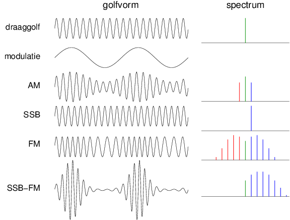
Is this an accurate illustration, particularly the depiction of the SSB wave in the time domain? ZFT (talk) 02:18, 5 January 2017 (UTC)
- Yes, that is exactly right. Of course, in a real-life application the modulating signal will not be a single sine wave. It will be a complex mix of frequencies spread over a band (the baseband), hence the sidebands will not be single lines in the frequency domain, but spread over a band by the same amount. SpinningSpark 14:41, 5 January 2017 (UTC)
- I think I found a much better diagram { http://www.survival.org.au/images/am1.gif }. Though, if the sidebands result from the modulation process, shouldn't they have a varying, not constant, amplitude? ZFT (talk) 19:03, 8 January 2017 (UTC)
- To put it another way, why does the total (carrier plus sidebands) AM signal in the time domain appear to have a constant frequency if it is composed of a set of three frequencies (the carrier and the sidebands)? ZFT (talk) 02:08, 29 January 2017 (UTC)
- Exactly. I'm with everybody who's not getting this and don't see a satisfactory answer here yet myself. A carrier sine plus modulated, per the traditional diagrams, should still always be at that one fixed single frequency, just varying in amplitude only. People have mentioned multiplying frequencies, but you're adding, not multiplying. Worse, the traditional diagrams in side view (frequency as X axis, amplitude as Y) show a fixed carrier wave on its frequency, and the sidebands as not a similar fixed frequency like the carrier wave, but a sort of truncated elliptical distribution centered on the sideband frequency, which means there's technically an infinite number of sideband frequencies in those two ranges. If the traditional overlay model is right, none of those sides should even exist, all the action is taking place on the carrier frequency only. And if the answer is a bunch of esoteric equations that mysteriously "decompose" all the information in that one single amplitude-modulated carrier of fixed frequency, what's to stop it similarly from decomposing somehow into not two sidebands but more of reducing amplitude? I put this exact same question to a couple of hams with Advanced certification or higher, and they just looked at me like they didn't even grasp the question, which makes me think they never bothered really understanding the subject themselves. Something here still doesn't make sense, which means the article may not yet either :-/ Chris Rodgers (talk) 21:17, 18 April 2020 (UTC)
The Fourier "spectrum" of a signal, is zero at every frequency where is orthogonal to . (The cross-correlation between and is zero.) That only happens when is also a pure sinusoid with a different frequency. (It can also happen at the same frequency if there is a 90° phase difference, but that's a different discussion.) As soon as we modulate in any way, the cross-correlation with a pure sinusoid is no longer zero. But it decreases to insignificant levels at values of far enough away from the frequency of Where the levels are significant, we call it "sidebands". Where they aren't, we approximate them as zero on a typical spectrum graph. That, in lieu of "a bunch of esoteric equations", is the explanation you're hoping for. Now the question is whether or not there is a place for it in the article.
--Bob K (talk) 00:21, 20 April 2020 (UTC)


- Read that back to your grandmother and tell me if she understands now where the sidebands come from. We should grope toward an explanation that explains that once you change the shape of a sine wave, you need additional frequency components to describe the shape of the resulting modulated waveform, which can be calculated using the Fourier transform. ( and that's what someone said 3 years ago, above). --Wtshymanski (talk) 22:27, 20 April 2020 (UTC)
I am perfectly happy to let someone else (meaning you, for instance) take over here and try to satisfy the readers who apparently have no clue what a Fourier transform is, and won't likely learn it from Fourier transform, which is written at a much higher level than this. But before leaving, I will say that my attempted answer only requires the reader to comprehend the simpler concept of cross-correlation, which is the basic element of a Fourier transform... but done over all frequencies. Thanks for letting me off the hook, and good luck... it's your problem now... Bob out.
--Bob K (talk) 23:50, 20 April 2020 (UTC)
- Wikipedia articles are perpetually in draft. You identified a key weakness in my attempt at explaining the origin of sidebands. How can we explain that to Granny in something that ends "...(and calculating the magnitude of these components is a process called a Fourier transform)." ? --Wtshymanski (talk) 19:34, 21 April 2020 (UTC)
- Yes, you're right, I apologize. But I don't have a better answer at the moment than the one you replaced. However I do have some time on my hands, so I will still think about it. There are almost 200 WikiLinks to this article. That is such a great strength of WikiPedia... we can write those other articles for both beginners and experts, without burdening the experts with relatively remedial concepts like the title of this talk segment (Where Do Sidebands Come From?). I imagine that most of the readers who end up here are in need of an answer written at a pretty low level. Maybe even cross-correlation isn't low enough. Or maybe there is a picture we can add that would do the trick... "worth a thousand words". --Bob K (talk) 12:21, 22 April 2020 (UTC)
- I think we should avoid using the math as if it's an explanation, and instead explain what's happening that the math is describing. ==Wtshymanski (talk) 23:03, 22 April 2020 (UTC)
- Yes, you're right, I apologize. But I don't have a better answer at the moment than the one you replaced. However I do have some time on my hands, so I will still think about it. There are almost 200 WikiLinks to this article. That is such a great strength of WikiPedia... we can write those other articles for both beginners and experts, without burdening the experts with relatively remedial concepts like the title of this talk segment (Where Do Sidebands Come From?). I imagine that most of the readers who end up here are in need of an answer written at a pretty low level. Maybe even cross-correlation isn't low enough. Or maybe there is a picture we can add that would do the trick... "worth a thousand words". --Bob K (talk) 12:21, 22 April 2020 (UTC)
- The originator of this question already knows what is happening... a signal at one [carrier] frequency is creating physically detectable energy at nearby frequencies. I believe he is asking why or how, which is physics. We generally cannot answer those questions... rather we observe and model them mathematically. Also, consider the textbooks that treat modulation theory. Mathematical modelling is the universal language.
- Another way to put it is that in a sense our friend isn't asking what does this mean?:

- I think Wtshymanski has a good why? answer - after modulation it's no longer a simple sine so can't be represented as a single frequency. A related question is, why does the carrier disappear? AM modulation is multiplication. When one of the terms is 0, the result is 0. When the modulator is 0, the carrier is suppressed. When the modulator is non-zero, it is always on its way to somewhere else so, through modulation, it is bending the carrier, changing not just the amplitude but also subtly changing the shape of the carrier. ~Kvng (talk) 14:59, 26 April 2020 (UTC)
LSSB and USSB[edit]
LSB is sometimes called LSSB, and USB is sometimes called USSB.Dima373 (talk) 19:40, 23 February 2008 (UTC)
- There is a subtle difference. LSSB refers to single sideband modulation based on the lower sideband. LSB is just the lower sideband, either on its own or as part of a modulation scheme (like AM or FM). SpinningSpark 19:51, 1 January 2017 (UTC)
0.75 MHZ or 1.25 MHz[edit]
Some broadcast television systems use a vestigal sideband with a nominal width of 0.75 MHz others use 1.25 MHz. 0.75 MHZ is obviously more economic in overall bandwidth terms but what (if any) are the benefits of 1.25 MHz ? 213.40.110.233 (talk) 23:39, 10 January 2009 (UTC)
- NTSC has the carrier 1.25MHz above the bottom of the channel, and 0.75MHz lower sideband bandwidth. As the filters aren't perfect, that goves the filters some space. Note that the IF filters have to fix this up, otherwise the frequency response will be wrong. Gah4 (talk) 06
- 26, 16 February 2022 (UTC)
SSB suppressed carrier in FM broadcasting[edit]
Omnia, a company that makes broadcast electronics including FM stereo encoders, has been experimenting with SSBSC for the L-R subcarrier in FM stereo broadcast. This press release has links to the company's white paper and to their notice of intent... interest... something in experimenting on the public airwaves to the FCC. They have received authorization for experiments. They claim the method is compatible with the existing receivers they've tested and that it results in (of course) a modest reduction in bandwidth of the broadcast signal. There is a claimed improvement in performance, particularly in susceptibility to multipath. I'm not really technically competent to write this up for the article, but it seems as if it's relevant. Jeh (talk) 13:13, 7 October 2011 (UTC)
- I think this is too specialised and 'advanced' a topic for this article, which ISTM exists to introduce sidebands to readers who haven't come across them before. Maybe it would be better covered in FM broadcasting, which goes into greater depth.--Harumphy (talk) 15:12, 7 October 2011 (UTC)
- It is also only experimental so far and if the only information is coming from the company press releases then we have no reliable sources to show this is a notable topic. SpinningSpark 16:55, 7 October 2011 (UTC)
- Valid points all. It is at least worth watching to see what comes of it. Jeh (talk) 20:44, 7 October 2011 (UTC)
- In any case, I don't think it applies to this article. It would apply for the discussion on the stereo subcarrier itself, or to AM-SC modulation in general. I haven't though about this for a while, but I believe that was discussion about AM stereo that puts on channel on one sideband, and the other on the other one. Mono receivers will the combine them, as usual. That would also go somewhere else. Gah4 (talk) 15:06, 21 February 2022 (UTC)
- Valid points all. It is at least worth watching to see what comes of it. Jeh (talk) 20:44, 7 October 2011 (UTC)
one word[edit]
Just wondering, is sideband a real word? Is it in the OED? Gah4 (talk) 06:27, 16 February 2022 (UTC)
- IEEE Std. 100 says "sideband" is a word. --Wtshymanski (talk) 06:00, 21 February 2022 (UTC)
- Yes: it is in the Oxford dictionary. Also in practically every other dictionary both English and American, so we can't even write it off to an ENGVAR issue. 81.154.179.214 (talk) 14:06, 21 February 2022 (UTC)