This is an archive of past discussions. Do not edit the contents of this page. If you wish to start a new discussion or revive an old one, please do so on the current talk page.
Hi everybody! I would like to join this so interesting discussion. I have noted for a long time that in electronics Negative resistance and its most popular circuit implementation - Negative impedance converter - are almost mysteries. What is more, they are real nightmares for students and not only for them:)
Browsing through the article I have been noting that it looks quite solid and scientific (especially the last part describing in details a scientific experiment with a lot of links pointing to original sources). However, frankly speaking, I am not sure if visitors would understand what negative resistance is from this page. In my opinion, reading this page, they will know what negative resistance is (for example, "a situation when current is a decreasing function of voltage"), but they will not really understand it...
From many years, I have been thinking about the phenomenon of negative resistance. Finally, I have managed to build my own philosophy about it; now, I would like to share my penetrations with you. Maybe, I have first to define accurately who I am and what my goals are. Simply, I am just a human being who loves circuits; so, I will expose here a "circuit viewpoint" at the phenomenon.
The point is that we are human beings needing something more than scientific facts, reports, formal explanations and definitions. In order to really comprehend the phenomenon of negative resistance (and of every new thing in this life), we need first to know what the general idea behind it is. Only, basic circuit ideas are in fact "non-electrical". They do not depend on the specific implementation (tube, transistor, op-amp etc.); they are eternal. So, we may find them in our routine. Then, let's ask the first question.
What is the basic idea behind negative resistance?
Extracting the general idea from our routine
Generally speaking, we may observe this phenomenon in situations where someone (something) interferes to some extent in our life. He/she/it may help or impede us in three degrees (under-, exactly- or over-). Negative resistance represents the last degree when someone "over-helps" or "over-impedes" us - see more examples in my page about the "over-helping" negative resistance (the dual page about "over-impeding" negative resistance is under construction). We can already make the first conclusion:
A negative resistance phenomenon is a process of injecting an additional excessive power to an existing power source.
Comparison between "ordinary" and negative resistance
Now, let's move to the electrical domain and answer the main question: What is negative resistance (resistor) versus ordinary resistance (resistor)?
A voltage source acting as a negative resistor (connected in series with the load)
Fig. 1a: An "ordinary" positive resistor
Fig. 1b: An "over-helping" voltage source
Fig. 1c: An "over-impeding" voltage source
In order to compare an ordinary "positive" resistor R with a negative resistor -R, let's assemble two circuits where these components are connected in series with the loads so that the same current passes through them. As a result, a voltage drop VR = R.I appears across the "positive" resistor R (Fig. 1a) and the same voltage VH = VR = R.I appears across the negative resistor -R (Fig. 1b). Only, the resistor R sucks the voltage V = R.I from the circuit (it is a voltage drop) while the negative resistor -R adds the voltage V = R.I into the circuit. So, a resistor acts as a current-to-voltage drop converter while a negative resistor acts as a current-to-voltage converter. The element named "resistor" is really a resistor while here the "negative resistor" is actually a voltage source, whose voltage is proportional to the current passing through it. Now, we can answer the main question "What is negative resistor?"; the answer is simple and clear.
A negative resistor is just a voltage source, whose voltage is proportional to the current passing through it. Shortly, a negative resistor acts as a "current-controlled voltage source".
If we connect the additional voltage source in the opposite direction versus the input voltage source (Fig. 1c), it will act as an "over-impeding" voltage source.
A current source acting as a negative resistor (connected in parallel with the load)
Fig. 2a: An "ordinary" positive resistor
Fig. 2b: An "over-helping" current source
Fig. 2c: An "over-impeding" current source
Now, let's assemble two circuits where these components are connected in parallel to the loads so that the same voltage is applied across them. As a result, a current IR = VL/R passes through the resistor R (Fig. 2a) and the same current IH = VL/R passes through the negative resistor -R (Fig. 2b). Only, the resistor R sucks the current from the circuit while the negative resistor -R injects the current into the circuit. The element named "resistor" is really a resistor while here the "negative resistor" is actually a current source, whose current is proportional to the voltage across it. Thus we have found another answer to the main question "What is negative resistor?"
A negative resistor is just a current source, whose current is proportional to the voltage across it. Shortly, a negative resistor acts as a "voltage-controlled current source".
If we connect the additional current source in the opposite direction versus the input current source (Fig. 2c), it will act as an "over-impeding" current source.
How do we make negative resistors?
An S-shaped negative differential resistor
"Natural" negative differential resistors...
...based on constant-voltage dynamic resistors . We may obtain them, if we begin dynamically decreasing the ordinary ohmic resistor. First, we decrease slightly the ohmic resistance R (section 1-2) thus getting decreased differential resistance. Then, we decrease considerably enough the ohmic resistance (section 2-3), in order to get zero differential resistance (a voltage-stable dynamic resistor, a voltage stabilizer). Finally, decreasing enormously the ohmic resistance (section 3-4), we go so far that the IV curve changes its slope; as a result, we obtain the desired S-negative differential resistance. In this way, following the sequence: ohmic > decreased > zero > S-negative differential resistance, we come to conclusion: An S-shaped negative differential resistor is actually an "over-acting" voltage-stable dynamic resistor.
Examples: neon lamps, thyristors etc. See also my new story about negative differential resistors:
...based on constant-current dynamic resistors. Similarly, we may obtain the dual negative resistors, if we begin dynamically increasing the ordinary ohmic resistor. First, we increase slightly the ohmic resistance R (section 1-2) thus getting increased differential resistance. Then, we increase considerably enough the ohmic resistance (section 2-3), in order to get infinite differential resistance (a current-stable dynamic resistor, a current stabilizer). Finally, increasing enormously the ohmic resistance (section 3-4), we go so far that the IV curve changes its slope; as a result, we obtain the desired N-negative differential resistance. In this way, following the sequence: ohmic > increased > infinite > N-negative differential resistance, we come to conclusion: An N-negative differential resistor is actually an "over-acting" current-stable dynamic resistor.
Examples: tunnel and Gunn diodes etc.
A general conclusion:The negative differential resistor acts as a dynamic resistor with considerably varying resistance.
Only, the negative differential resistor that we have obtained is not a true negative resistor as it does not contain a source; it is just a part of such a negative resistor. In order to get a true negative resistor, we have to connect in series an additional constant voltage source:
A negative resistor connected in series with the load
Fig. 3a: An "ordinary" positive resistor
Fig. 3b: An "over-helping" negative resistor
Fig. 3c: An "over-impeding" negative resistor
A negative resistor connected in parallel with the load
Fig. 4a: An "ordinary" positive resistor
Fig. 4b: An "over-helping" negative resistor
Fig. 4c: An "over-impeding" negative resistor
Negative resistor applications
Negative resistor acting as an amplifer
It is considered that a negative resistor can act as an amplifier. If this is true, are there any difference between a negative resistor and an amplifier? If yes, what is the difference? Let's clarify the topic.
What is amplification?
I hope you agree with me that amplification is impossible. We cannot amplify energy (power); we can only regulate it. Then what is amplification? How do we amplify? How do we make an amplifier? It sounds bluntly, but it is true that in (analog) electronics we use the possibly silliest idea for this purpose.
In order to amplify some small input power (in electronics, usually presented by input voltage), we get many times bigger (at least, VPS = K.VINmax) power source (a constant voltage source acting as a power supply) and then, imagine, we throw out the excessive power?!? An example of this absurd: in order to "amplify" 10 times 1V input voltage by a 24V supplied amplifier, we throw out (as a heat) the power according to the rest 14V (in energetics, they never do that!) Doing that, we actually dissipate, attenuate power. As a result, there is not amplification; there is only attenuation!
How do we make an "ordinary" amplifier?
Components. Following the silly idea above (obviously, we have no choice), we may assemble an amplifier by using only two components: a power supply and a regulating element.
A power supply. According to the chosen structure (see below), we need a constant-voltage or a constant-current power supply.
A regulating element. The function of this component is to resist the current (in order to dissipate a power), proportionally to the magnitude of the input voltage source. So, it acts as an electrically controlled resistor (carbon microphone, a tube, a transistor etc.) whith input and output part.
In the 4-terminal regulating elements (e.g., carbon microphone, magnetic amplifier etc.) the input and output part are electrically separated; so, they do not interact each other.
In the 3-terminal regulating elements (e.g., tubes, transistors etc.) the input and output part are electrically connected by the common terminal (emitter, base, collector etc.) In some arrangements (e.g., common emitter amplifier), they do not interact each other while, in other cases (e.g., common collector amplifier), the output influences the input by feedback.
But what do we have to do, if we have only a humble 2-terminal regulating element, which input and output parts are the same? If you do not guess, see the answer below.
Amplifier structures. We can connect these components, according to the basic electrical circuits, in series or in parallel to the load.
A series amplifier. In some cases, we connect in series a constant-voltage power supply, the output part of the regulating element and the load.
A parallel amplifier. In other cases, we connect in parallel a constant-current power supply (constant-voltage source + resistor), the output part of the regulating element and the load.
How do we make a negative resistance amplifier?
A negative resistor acting as a regulating element. In the past, striving to build an extremely simple amplifier by using a 2-terminal regulating element, maybe they asked themselves, "How to reach the regulating element, in order to control its resistance?" or, "Where to apply the input signal?" Then they guessed to use an odd regulating element - dynamic resistor, which resistance depends considerably on the current passing through the same element (i.e., a negative differential resistor). In this odd 2-terminal element, the input and the output part are the same; so, they could apply the input signal to the output part. It looks quite strange, doesn't it?
An amplifier structure. So, we can build an odd negative resistance amplifier by connecting in series all the components needed: a constant-voltage power supply V, a negative differential resistor, an input voltage source VIN and a "positive" resistor. The negative differential resistor and the "positive" resistor constitute a voltage divider, which ratio depends on the input voltage. So, we may think of this circuit as a voltage divider supplied by a slightly varying voltage source V + VIN.
An amplifier operation. When we vary slightly the input voltage, the negative differential resistor changes considerably its resistance according to the input voltage; so, the voltage divider changes noteceably its ratio. As a result, the voltage drops across the "positive" and negative resistors vary considerably; so, we may use some of them as an output voltage.
Negative resistor acting as a bistable component (a flip-flop)
Interesting. Perhaps you could generalise it further, and say that all resistances, whether negative or positive, are current-controlled voltage sources. That way, you could merge your two diagrams into one. Positive resistances have a positive current-to-voltage coefficient, which causes the product of voltage and current, or the power consumption, to be positive. They do not therefore need a power source (although you could make such a device with a power source - I suppose that's what an active load is). Negative resistances have a negative I-V coefficient, which causes the product of current and voltage to be negative, and hence they emit power. They therefore need a power source. Or am I overcomplicating things? --Heron 19:04, 9 July 2006 (UTC)
Neron, thank you for the support. Really, Wikipedia is a great idea; now, I have the feeling that I am in the right place at the right time. Imagine, I am an initial excitation voltage source, which experiences a decrased resistance because of you acting as a "helping" voltage source:) If you continue working in this direction, I will experience zero:)) and finally negative resistance:)))
I accept your text; I admire its laconism and precision. You have made it just for an encyclopedia. Maybe, we might generalize the two components into one block diagram of a current-to-voltage converter.
From one side, to say that an ordinary "positive" resistor is a current-controlled voltage source sounds quite strange. Generally speaking, sources and loads (for example resistors) are converters - sources transfer energy from outside world to circuit while resistors transfer energy from circuits to outside world. However, there is something confusing to use here the term current-to-voltage converter as it is rather informational than energetical device. Actually, we do not convert current into voltage; we just change the carrier of analog information (current with voltage).
From the other side, you are right to think of a resistor as a voltage source - this is just a Norton's idea to build a voltage source by using a current one (Norton's theorem). The situation is similar to the dispute "Is a voltage divider a voltage source?" Let's think a little more...
Finally, don't you think that there is something confusing in the fact that ordinary resistance is something negative (harmful) but yet it is named "positive" resistance? Also, note that its power disappears but we say that it is positive. And v.v., why although a negative resistor add energy into circuit, we name it "negative" resistor? Don't you think that is more natural to reverse this terminology (of curse, we will not afford to do that:)
Hi again! I have finally made a decision about your suggestion to combine the positive and negative resistors into the concept of current-controlled voltage source. Sorry, I can't accept it because of reasons above. I will repeat them again below.
A "positive" resistor is just a resistor. Really, a voltage appears across the resistor but it is not its voltage; this is the voltage of the excitation electrical source (current source or a voltage source with a series connected resistor). The whole combination current source + resistor acts as a source; similarly, the combination voltage source + voltage divider acts as a new derivative voltage source.
Again, the "positive" resistor is a load while the negative resistor is a source. They both are converters. --Circuit-fantasist 18:01, 21 July 2006 (UTC)
AFAIK, any source that adjusts its o/p voltage to keep its output current constant has a -ve o/p impedance, so if the load impedance increases, so will the o/p voltage and this is equivalent to the source having its o/p impedance being reduced. This is basically a constant current source action. Does this make sense, or am I way off track...? Rohitbd 12:16, 10 July 2006 (UTC)
There isn't a voltage divider connected in the non-inverting input of the op-amp INIC; as a result, the op-amp acts as an "over-impeding" voltage source producing two times higher compensating voltage in point B.Hi, Rohitbd. Thank you for joining the dispute. The topic of constant current creating is very interesting. That is why, I have created a special page about the philosophy of constant current source creating and a few more specific pages about practical CCS. Yes, I think that when the over protection circuit of a power supply comes into operation, it usually begins behaving as a CCS (as far as know, there are also other circuits with trigger action).
We may use CCS concept to introduce the second kind of negative resistance (I have named it figuratively "over-impeding" negative resistance). The ordinary CCS keeps a constant current by varying its internal voltage or resistance. In order to convert this circuit into NIC, we have just to "mislead" the op-amp making it "over-act". For example, compare the two circuits of Op-amp Widlar current source and INIC on the right and you will see that there is only one difference between them - the voltage divider R3-R4. In the first circuit, it prevents the "over-compensating". As a result, the voltage VB follows exactly the voltage VA (bootstrapping). In the second circuit, there isn't a voltage divider. As a result, the op-amp produces 2 times higher voltage VB than VA and a negative resistance appears. Circuit-fantasist 19:27, 11 July 2006 (UTC)
Your explanation is interesting from an intuitive point of view, but it's really quite simple mathematically and electrically. The sign of the voltage drop in your above drawings is opposite for positive and negative resistances. Heron's observation that negative resistance is a power source rather than a power sink is a direct consequence from the definition of power (or energy). Rohitbd's observation is partly correct. A regulated power supply appears as a negative resistance at it's input. The output impedance is zero for a voltage source and infinite for a current source. Madhu 14:12, 10 July 2006 (UTC)
Hello, Madhu. Thank you for the feedback. As I can see, we are quite different person - I rely mainly on my imagination, intuition and emotions while you rely on reasoning and formal analysis. Wikipedia gives us a chance to combine, not to oppose, both the approaches: I might reveal circuit phenomena and build circuits; you might analyze them. Famous circuits are invented by using this complementary principle, for example CMOS. Let's solve "qualitative" problems (introducing, explaining and revealing the basic ideas behind circuits) by qualitative means and "quantitative" ones - by using quantitative means.
I have corrected the sign of VI = R.I on fig. 2 and removed some confusing signs in the text.
What do you mean saying "A regulated power supply appears as a negative resistance at it's input"? --Circuit-fantasist 17:26, 12 July 2006 (UTC)
You can look at it both intuitively and analytically. An ideal regulator is 100% efficient, so all input power is avaiable at the output, i.e. power is conserved. The only difference is the input/output voltage. If the output voltage is constant and connected to a fixed resistive load, the output power is constant. The input power must also be constant since power is conserved. If the input voltage is increased, the input current drops to maintain constant power. This is negative differential resistance: current goes down when voltage goes up (and vice-versa). It's not hard to relax the 100% efficiency constraint and show that non-ideal regulated supplies also exhibit negative resistance.
Here are a couple of negative resistance circuits which might not be intuitive: Wien bridge oscillator and Colpitts oscillator. Of course, one could intuitively argue that any harmonic oscillator exhibits negative resistance at some port. Madhu 20:36, 12 July 2006 (UTC)
Thank you for the example; I have already known another interesting circuit phenomenon. As far as I can see, you mean a "clever" voltage regulator (for example pulse regulator), which does not regulate the output voltage by dissipating the surplus power on an analog regulating element (transistor). Instead, it "observes" the output voltage by a feedback and changes the pulse width thus regulating the current needed. Another more primitive but clear example: someone regulates AC voltage by observing it on the transformer's output (that is, using feedback) and changing the transformer ratio (for example, switching over the winds or moving a slider). Maybe, (hydro) power stations in energetics use this phenomenon when regulate their electrical outputs; maybe, they behave as negative resistors at their hydraulic inputs? Well, let's finalize these thoughts in a conclusion:
The input part of the circuit consuming a constant power behaves as a negative resistor.
Voltage versus current. However I am confused by the assertion "This is negative differential resistance: current goes down when voltage goes up (and vice-versa)" or the same "current is a decreasing function of voltage" (Negative resistance). Look at the picture of an op-amp NIC that I have inserted above; it has a negative resistance but here the current goes down when the voltage goes down and vice-versa (similarly to the behavior of a bare resistor)! It comes out that both the cases exist; therefore, there is no sense in this assertion!? What do you think about this paradox?
I'm missing your point. If current goes down as voltage goes down, how is that negative resistance? Isn't that the definition of positive resistance? Madhu 22:11, 13 July 2006 (UTC)
Negative resistor versus amplifier. Madhu, since you are so clever, can you answer what the relationship is between a negative resistor and an amplifier? As we know, it is considered that a negative resistor is an amplifier. If it is true, are there any difference between a negative resistor and an amplifier? If yes, what is the difference? I will show my viewpoint in "2.1. Negative resistor acts as an odd amplifier" but now I give an opportunity to express first your view:)
I wouldn't call myself clever, in fact, I'm fairly sure I'm not ;-) To answer your question, I would say that a negative resistor is like a one port amplifer. Of course, this is entirely my opinion. Others probably have their own way of looking at it, and that's perfectly fine. I personally don't have much interest in debating opinions, but that's just me. You're more than welcome to come up with your own answers in your own way, but I prefer to analyze circuits mathematically. It works for me. Madhu 22:11, 13 July 2006 (UTC)
Hi Madhu! Sorry for the delay; these days, I was seized by the idea how to evade NOR (see below). Now, I would like to resume the discussion about the negative resistor acting as an amplifier. Maybe, your idea to think of negative resistor as a one-port amplifier is great. Only, there is a "little" problem - I do not know what a one port amplifier actually is:) Can you give me more info about it? It would be very well, if it is a 2-terminal device; then, we might merge our explanations.
Madhu, thank you for your correct replies. As I can see, for now I manage to keep some dialogue only with a few Wikipedians and you are one of them. I have the feeling that I become disappointed in the Wiki society in the area of electronics:( There are too many people dealing with routine editorial activities and only few people eager to discuss circuit phenomena:( --Circuit-fantasist 18:04, 20 July 2006 (UTC)
Well, I don't think my idea about the one port amplifier is great at all, it's just the first answer that came to mind. By one port, I mean that the input and output are the same. Conventional amplifiers usually have two ports: a distinct input and output. Further, a negative resistor isn't a great replacement for a conventional, two port amplifier, IMHO. You bring up some interesting topics, but as you say, we probably look at circuits differently. If you like, we can continue the discussion offline. You can find my email address here: Madhu 22:15, 20 July 2006 (UTC)
Thank you for the elucidation. I am happy that I think in this direction also. I don't know why but I like 2-terminal devices, maybe because of their perfect simplicity. I have found an interesting message about this topic. See also an interesting picture comparison between the positive and negative resistance corresponding to my wievpoint.
Madhu, it is interesting for me to communicate with you. Of course, I will use the email, if the topic discussed is not so interesting for the other Wikipedians. --Circuit-fantasist 19:38, 22 July 2006 (UTC)
I don't think that Wien bridge oscillator and Colpitts oscillator are non-intuitive. I think that they have invented them and then they have hidden the key:) I haven't yet an intuitive notion about them but I know I will ever have. For now, I have some intuitive notion about Hartley generator. --Circuit-fantasist 20:17, 13 July 2006 (UTC)
I didn't have an intuitive understanding of them either, until I did the analysis. In my opinion, the Hartley and Colpitts circuits are electrical duals. If you can understand one, you can understand the other. Madhu 22:11, 13 July 2006 (UTC)
A damper
I hate to put a damper on all this enthusiasm, but we must be careful here to abide by WP:NOR. Ie these ways of explaining things are OK if someone else has already published them. Yes?--Light current 02:09, 12 July 2006 (UTC)
Well, merely coming up with a new way of explaining something probably isn't OR, just good writing. But coming up with a new concept certainly would be OR.
Well.. you know Atlant, Im not sure about that. Ive put forward a number of new explanations of things only to be shot down in flames by some editors firing the NOR missile at me! 8-(--Light current 23:49, 12 July 2006 (UTC)
Hi Light current, Atlant and all members of Wikipedia society in this area of electronics! I realize that I have disturbed to some extent your calmness:); so, maybe I have to say some words about me, my reasons and my intentions. Simply speaking, I have to say what I (will) do on talk and article pages of Wikipedia.
Yes, I do original research!
Honestly, I realize that I actually do an original research on talk pages of Wikipedia contrary to NOR. According to its definitions, I do "research that consists of collecting and organizing information from existing primary or secondary sources (generalization, analysis, synthesis, interpretation, or evaluation of information or data)..." What is more, my explanations on talk pages are based on my "self-published resources" available to readers from my web site of circuit-fantasia.com. In addition, I do all the "bad" things listed in What is excluded? As far as I know, there is nothing wrong with it, if I stay at talk pages. But what have I to do, in order to join the article pages abiding by NOR? Below, I share some tips about how to evade Wikipedia NOR barrier.
But yet, how do we evade NOR? (a tip for creatively thinking Wikipedians)
My idea is extremely simple - to explain circuits so simply, clearly and evidently that there is no any need to verify these explanations (NOR stipulates such a possibility - to use sources "the accuracy of which is easily verifiable by any reasonable adult without specialist knowledge..."). For this purpose, I present circuits relying only on human (web visitor's) experience, imagination and intuition. I implement this approach by using a 3-step "scenario" (see my teaching philosophy). First, I extract the basic idea from many everyday situations formulating it verbally and in a form of block-diagram, then I show the possibly simplest equivalent electrical circuit diagram and finally I draw the specific electronic circuit solution.
You probably guess why I can't cite "verifiable sources", which reveal circuit phenomena - just because there are not such sources! I have been looking for them on the web from years but I have not found yet. I don't know why but it is true that the existing "verifiable sources" are dull and formal. Maybe, their authors pursue other goals (for example, to climb up the scientific ladder); that is why they make the simple complex while I try to make the complex simple, the simple - simpler and the simpler - simplest.... Figuratively speaking, I am just the boy from Andersen's story who says "The King is naked!":)
I have refused a long time ago to publish my ideas in the so-called "verifiable sources" since they consider this human-friendly approach as a non-scientific (in the bad sense of the word). Note - they do not reveal the ideas behind circuits but if you do that, they will probably shout, "This is non-scientific"! I can't stop showing some example of this paradox; here is such a story about it.
An example of this approach
Bob Pease's viewpoint at transimpedance amplifier
Electronic design magazine is an extremely reputable source and Bob Pease is an extremely reputable author. Well, let's then try to understand what the op-amp actually does in the circuit of a transimpedance amplifier following the link from the bottom of this Wiki page pointing to Bob's reputable article What's All This Transimpedance Amplifier Stuff, Anyhow?. I have formatted his text in bold italic and inserted my comments into the original text between his thoughts.
"One of the first things you learn about operational amplifiers (op amps) is that the op amp's gain is very high", Mr. Pease begins his story. Only, the gain is the most
insignificant op-amp's feature, if we try to understand what the op-amp does in the circuit discussed. What is the problem to be solved?
"Now, let's connect a feedback resistor across it, from the output to the −input (Fig. 1)." I ask, "Why?" Is there any reasonable need to do that? Because we, human beings, do something, only if there is some reason to do that.
"When you put some input current into the −input..." Again, I ask, "Why?" What is the need to put the current just into there?
"...(also known as the summing point),..." Is the −input a summing point here? If yes, what does it sum here (recall that the op-amp has extremely high input impedance)? As far as I know, we need at least two inputs and one output, in order to sum something.
"...the gain is so high that all of the current must go through the feedback resistor." Can you see any direct connection between the very high gain and the behavior of the current? Has the current any other alternative to flow? No, as the op-amp has extremely high input impedance.
"So, the output will be VOUT = −(Iin × Rf). That's neat." Again, "Why?" Can you see any connection between this speculation and the previous one from above? It is only evident (according to Ohm's law) that the voltage drop across the resistor R is Vr = Iin × Rf; however, I wonder why "the output will be Vout = −(Iin × Rf)"? I would like to know why.
"While we used to call this a "current-to-voltage converter," which it is indeed, it's also sometimes referred to as a "transimpedance amplifier," where the "gain" or "transimpedance" is equal to RF", concludes Mr. Pease at the end.
Now, answer honestly to my questions. What have you understood from this reputable source? Have you known what the problem actually is? Have you realized how the problem was solved? Have you made sense of connecting an op-amp? Do you understand what it actually does in this circuit? Simply speaking, what is the basic idea behind the circuit? Can you elaborate it, in order to get circuits that are more complex (for example, circuits with negative resistance)? Can you simplify it, in order to get circuits that are simpler (for example, op-amp ammeter)?
Try to find ahswers to these questions yourself. As for me, I will prepare a human-friendly story about this legendary circuit and will place a link to this "non-verifiable" source on transimpedance amplifier page. This circuit deserves attention. --Circuit-fantasist 07:59, 16 July 2006 (UTC)
My viewpoint at transimpedance amplifier
As I can see, there aren't any suggestions; as usual, I have first to expose my viewpoint. If I have to express briefly the main idea, I will say:
In transimpedance amplifier, the op-amp compensates the voltage drop across the resistor adding as much voltage as it loses; the compensating voltage serves as an output voltage.
Using an idea of compensation is not a good way to think of it. Think of it as servoing. In an idealized, simple transimpedance amplifier circuit, an injected current most go somewhere, it's not going into the amplifier. The current must be drawn through the feedback resistor. Well, how does that happen? The op amp must create an output voltage that forces this to occur, and using the inverting input allows the resulting output voltage to stabilize at the required output voltage. (I think you know that using the non-inverting input would drive the output to a rail.) So when you inject a new current into the circuit's input, the output voltage slews in a direction towards the voltage that will drag all the input current through the feedback resistor and then settles (if everything is stable), perhaps oscillating a little, on the exact required output voltage. It's really very simple, but you have to understand current, current sources, and the physics of having a complete circuit (from source to sink). (I hope you're not offended by that last comment, it is not intended. I remember when I was learning about these things, it took a while. And BTW most (even PhD) researchers don't know that they're supposed to use transimpedance amplifiers to convert a photodiode's output to a voltage. If you don't do it, you can create an output that sorta looks ok so they say, well it looks like a pretty go presentation of the input light signal, and perhaps it's not necessary to get a better signal, but it is far from a linear representation of the input current. It's one of those gotchas.) blackcloak 17:00, 28 July 2006 (UTC)
Hi Blackcloak! Thank you for the feedback. This subject is extremely important and interesting for me that I can discuss it as long as you want:) IMO, there isn't any contradiction between as; actually, we both think similarly. Maybe, the problem is that I have gone too far trying to penetrate in these phenomena; then, I have gone too far trying to reach the perfect simplicity in presenting them to students.
Browsing through your text I can see that you have thoroughly explained how the op-amp does the servoing (how it keeps the virtual ground). Yes, this is wonderful; I have also shown the op-amp action step-by-step in a flash movie dedicated to op-amp inverting summer (transimpedance amplifier is an important part of this circuit). Only, Blackcloak, believe me, this is insufficiently. As human beings, we need before to know why it does this work! Also, we need to know what problem the op-amp solves (why have we connected it there?). Simply speaking, we need to know what the basic idea is.
Many ideas can stay behind some specific circuit implementation but only one of them is the main, essential, substantial idea. In order to understand and then to explain really the circuit discussed, we have first to reveal and then to show this idea. For the circuit of the so called transimpedance amplifier, the main idea is exactly compensation, not negative feedback (servoing). Negative feedback is a great idea; but here, negative feedback is just a possible way of implementation. Compensation and negative feedback are not exactly equivalent ideas. We might make (passive) compensation without negative feedback and v.v. - (series) negative feedback without compensation.
Circuits with parallel feedback possess the property to interfere in the input sources - they may "help" or "oppose" the excitation voltage source. In the circuit of transimpedance amplifier, the op-amp "helps" the input source. It acts just as a small battery, which adds so much voltage as it loses across the resistor R. See how simple it sounds - just add a small battery in series with the resistor and make its voltage to be equal to the voltage drop across the resistor! In order to understand this bare truth, you needn't to know what servoing is; we just do it! For this purpose, we usually copy the "harmful" voltage drop across the resistor. The perfect "copying" is "active copying" (that is, negative feedback). That is why, we use it here. Let's say it again by little rewording.
In transimpedance amplifier, we (that is, the op-amp) copy the voltage drop across the resistor by using a negative feedback, then add the "copy" voltage into the circuit and finally use the compensating "mirror" voltage as an output voltage.
If you have time and enthusiasm enough, please visit the resources below that I have dedicated to this great idea (compensation, removing voltage by an "antivoltage", "helping", "zeroing" etc.)
Op-amp circuit builder shows my "great" penetration into these circuits. See the introduction (especially page D); then click on the components of the library, in order to build various circuits with parallel negative feedback.
Blackcloak, if I have an inspiration enough during the holidays, I will create a page about transimpedance amplifier especially for you:) --Circuit-fantasist 09:24, 29 July 2006 (UTC)
Blackcloak, where are you? You have disappeared just like a voltage drop across the resistor in the circuit of a transimpedance amplifier:) I have also disappeared for a week, in order to create my new page about transimpedance amplifier (as you can see, I keep my word). I would like to dedicate this exciting story about the legendary circuit to you. Only, there is a small problem - I don't know who you are actually:) --Circuit-fantasist 19:15, 5 August 2006 (UTC)
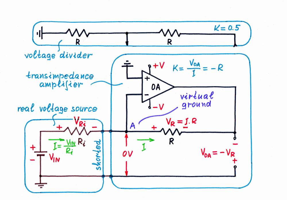
If I have to express in details the main idea, I will build the circuit in three successive logically connected steps. In the beginning, imagine we have to measure a current flowing through a part of some circuit (for example, imagine that we have to measure the current acquired from a real voltage source when it is shorted). However, we have a voltmeter instead an ammeter; so, we decide to convert the current into voltage. For this purpose, we break the circuit and connect a resistor R acting as a simple current-to-voltage converter.
What does the op-amp actually do in the circuit of transimpedance amplifier?
Step 1: Passive current-to-voltage converter
Step 2: Active current-to-voltage converter
Step 3: Op-amp current-to-voltage converter
Step 1: The problem. Only, a problem appears here: from one side, the voltage drop VR = R.I across the resistor (the output voltage) is useful for us; from the other side, this voltage is harmful as it enervates the excitation voltage (not shown on the picture). As a result, the current IIN decreases. What do we do to solve this contradiction?
There is no problem and there is no contracdiction. A current source is a current source, the voltage required to create the current is continuously varying (if necessary) to produce the desired current. blackcloak 17:00, 28 July 2006 (UTC)
I have clarified the arrangement above. I mean the common case - a real voltage source feeding the circuit (see this picture of a transimpedance amplifier). Well, I will discuss the situation with a great pleasure:)
You say, "A current source is a current source, the voltage required to create the current is continuously varying (if necessary) to produce the desired current." Right, this is one of the possible ways of creating a constant current source - by simple varying the excitation voltage or by negative feedback (the best solution). In this arrangement, the excitation voltage source (as a part of a constant current source), increasing additionally its voltage, compensates the losses into the imperfect current load (and not only them). It is wonderful! Unfortunately:(, in the most cases, we can't do that trick as we just can't reach (can't drive) the excitation voltage source! An analogy: can we control the sun, in order to adjust the light or the temperature inside the room:)?
That is why, we apply more frequently the other trick - we connect an additional voltage source, which compensates (only the local) losses into the imperfect current load. An analogy: we connect additional light or thermal sources inside the room, in order to "help" the sun (instead to control directly it).
In this way, we actually convert the imperfect current load into a perfect one with zero resistance (a kind of an active "superconductor":) You probably guest that using this technique, we can make almost ideal diodes without VF, "botomless" capacitors with infinite capacitance, perfect ammeters with zero resistance etc. Another advantage of this trick is using the compensating "anti-voltage" as an output voltage; so that we can connect as much low resistance load as we want - see the explanations below. --Circuit-fantasist 10:30, 29 July 2006 (UTC)
Step 2: The remedy. Obviously, we have to compensate the voltage losses across the resistor R. For this purpose, we connect an additional voltage source VH and adjust its voltage so that VH = VR. As a result, the "harmful" voltage VR and the resistance R disappears; the point A becomes a virtual ground (VA = 0). Actually, the additional voltage source VH "helps" the excitation voltage in its efforts to create the current IIN. Note that the two voltage sources are connected in series, in one and the same direction (- +, - +) so that their voltages are added. Then we take the compensating voltage VH = -VR = -R.I as a "mirror" output. The advantage: the load consumes energy from the "helping" voltage source instead from the excitation voltage source.
Step 3: The implementation. Finally, we make an op-amp do this donkeywork. Now, it "observes" the virtual ground and adjusts its output voltage VH = -VR = -R.I. See also:
A differential negative resistance component can also be employed as an amplifier. A tunnel diode is a good example. THe lede says the component must contain an energy source. That is not correct. --Light current 22:02, 2 August 2006 (UTC)
How can it be used as an amplifier if it has no energy source? — Omegatron 13:41, 3 August 2006 (UTC)
Well there must be an energy source somwhere but not necessarily in the component. Put a neg diffl res device across a tl. Rather than act as an attenuator (which a pos res would) it acts as an amplifier. THe energy comes from dc supplied by the line. 8-)--Light current 13:47, 3 August 2006 (UTC)
Hi everybody here! You carry on very, very interesting discussion! Let me join it. Here are a few thoughts about the topic (discuss). For more explanations, see above Negative resistor acting as an amplifier (discuss).
In the beginning, let's say that amplification is impossible. We cannot amplify energy (power); we can only regulate (attenuate) it. For this purpose, we need regulating elements, which do that work.
The classic 3-terminal regulating element (e.g., tube, transistor etc.) acts as an electrically controlled resistor with separate input and output ports. The voltage (current) applied across (through) the input port controls the resistance between the two terminals of the output port.
The odd 2-terminal regulating element (e.g., tunnel diode) acts as an electrically controlled resistor, which input and output are the same. The voltage (current) applied across (through) the two terminals of the element controls the resistance between the same two terminals. In order to do that magic, such a regulating element is actually an "over-acting" dynamic resistor, i.e. negative resistor.
In order to build such a Negative resistance amplifier, we may connect in series an input voltage source, a constant-voltage power supply, a "positive" resistor and a negative differential resistor. When the input voltage varies slightly, the negative differential resistor changes considerably its resistance according to the input voltage; so, the voltage divider changes noticeably its ratio. As a result, the voltage drops across the "positive" and negative resistors vary considerably; so, we may use some of them as an output voltage.
In this arrangement, the differential negative resistor is not an amplifier; it is just a part of an amplifier (the differential negative resistor is just a 2-terminal regulating element). The combination of the differential negative resistor acting as a regulating element and the power supply constitutes an amplifier:
Differential negative resistor + power supply = negative resistance amplifier
From other viewpoint, this combination forms a truly negative resistor:
Differential negative resistor + power supply = truly negative resistor
To obtain a negative resistance characteristic in a circuit using only positive impedance components, it is necessary to apply positive feedback at some point in the cct by means of an amplifier supplied by a suitable energy source.
Discuss--Light current 22:09, 2 August 2006 (UTC)
Maybe reword that a bit. If you say positive impedance, that might exclude capacitors, which have a negative reactance and small positive series resistance (or large parallel resistance). Arguably, an ideal capacitor has a negative impedance. How about "using only passive components with non-negative resistance"? Maybe reword "positive feedback" also, it could be a negative feedback amplifier and 180 degree phase shift. Madhu 20:06, 3 August 2006 (UTC)
Good points . I think about it some more! 8-)--Light current 22:42, 3 August 2006 (UTC)
Hi Light current and Madhu! Thank you for the posing so interesting problem for discussion. Here, I will try to expose my viewpoint at the topic. I hope that you will scrutinize my speculations and will react to them (I have not yet searched the web about this topic).
There are different kinds of feedback arrangements in an N-shaped IV curve of a negative differential resistor.IMO, in a circuit containing negative resistor, we may observe all the three possible situations:
there is negative feedback,
there is no feedback,
there is positive feedback.
Lets for concreteness consider a simple circuit, consisting of three connected in series components: a voltage source V, a "positive" resistor Ri (it might represent the internal source resistance) and a negative differential resistor -R. Depending on the kind of the negative resistor and the interrelation between the two resistances (the magnitude of Ri versus R), we may observe the cases below:
N-type negative resistor (based on an "over-acting" current-stable dynamic resistor)
Ri < R - there is negative feedback
Ri = R - there is no feedback
Ri > R - there is positive feedback
S-type negative resistor (based on an "over-acting" voltage-stable dynamic resistor [1])
Ri < R - there is positive feedback
Ri = R - there is no feedback
Ri > R - there is negative feedback
There are different kinds of feedback arrangements in an S-shaped IV curve of a negative differential resistor.Well, let's consider the picture on the right (only suppose that there is an ohmic resistor Ri instead the constant current source showed). Imagine that we have created this curve by applying different kinds of feedback arrangements as follows:
Section 0-1, ohmic resistance, we have not applied any feedback.
Section 1-2, decreased differential resistance, we have applied only imperfect negative feedback (e.g., by using an amplifier with little K).
Section 2-3, zero differential resistance, we have applied only perfect negative feedback thus obtaining a voltage stabilizer (Ri > R).
Section 3-4, negative differential resistance, we have added small positive feedback to the existing negative feedback (still Ri > R).
Then, if we make equal the positive and the negative feedback (Ri = R), we will have no feedback again.
Finally, if we increase the positive feedback so that it becomes stronger than negative one (Ri < R), we will obtain a flip-flop (memory) component.
I have finally realized why there is a need of positive feedback in negative resistance circuits. If you want, we might discuss this extremely interesting topic. Circuit-fantasist 11:25, 30 September 2006 (UTC)
wish: show the graph rotated too
Could the main graph also be drawn as V against I? It would be enlightening to see dV/dI as the actual gradient.
I don't feel that this qualifies for fair use because it could easily be recreated with a free-use image. Kevin 12:49, 1 August 2006 (UTC)
It is needed to show the device as she presented it. — Omegatron 13:35, 1 August 2006 (UTC)
I'm deleting it (and the other image) for the reasons Kevin said. You can easily recreate a diagram containing the same information, and source the information to the paper by Chung. Fut.Perf.☼ 12:11, 11 February 2007 (UTC)
Actually, I've had second thoughts and I'm undeleting it again. See image page for rationale. Sorry, my first day on the replaceable-fair-use speedy deletion queue. Fut.Perf.☼ 14:23, 11 February 2007 (UTC)
The basic idea behind the negative resistance phenomenon
Neron, my approach is first to extract the general non-electrical idea and then to apply it in the electrical domain. From this viewpoint, the non-electrical idea is more general that the electrical one. That is why, I have placed a general conclusion in the beginning of the first section.
By the way, I realize that this page and the other pages where a have contributed have become lengthy (I have discussed this with Alfred in the end of Talk:Current_source. Maybe, I will begin implementing my circuit stories as Wikibooks and will reduce the size of my Wikipedia contributions. I would be happy, if you help me to simplify and make the Wiki articles concise. Regards, Circuit-fantasist 17:16, 11 April 2007 (UTC)
True negative resistance device
I would like to point out that there is a device that exists that exhibits negative resistance - even for a short period. This is an arc lamp during the keep-alive portion. If one looks at the V-I curve for an arc lamp, the far left portion of it, where the current is small, the voltage has a negative slope.
If it's like the arc discharge characteristic on this page or this page then it's another example of negative differential resistance. At no time is the sign of the voltage opposite to that of the current. --Heron 19:45, 2 May 2007 (UTC)
Circumlocuitous, obfuscatory twaddle
This is the most confusing Wikipedia article of the many thousands that I have (mostly) had the pleasure to read. I stuggled to understand what was written even though I have a degree in physics, an IQ of 168, and work in electronics. Heaven help the lay reader whom Wikipedia is directed at.
The article is convoluted, overly-wordy, and appears to be too long for the subject matter. The drawings are quaint but not particularly illustrative. In fact, it reads like a webpage from one those free energy/oil conspiracy nutters. The whole things smacks of Single Author Syndrome. Others have made some attempts at tidying up but that has been like putting a Band-Aid on somebody who has fallen six storeys onto the footpath/pavement/sidewalk.
This article is in dire need of major surgery by someone with a clear grasp of the concept and able to write encyclopediacly (if that is a word). Unfortunately, that person is not me since I don't know any more about negative resistance than when I first started reading the article.
Secret Squïrrel, approx 02:40, 25 January 2008 (Earth Standard Time)
I am in complete agreement. For reasons I don't understand, negative numbers seem to cause a lot of trouble! It sounds like you are as qualified as anyone to perform the surgery. I think many have given up (myself included). Madhu (talk) 22:14, 22 February 2008 (UTC)
I also agree. The idea seems simple - sometimes when you produce a circuit model of some device (such as semiconductor or the equivalent circuit of an induction machine (motor or generator, which should be familiar to any electrical engineer)) a physical phenomena occurs which can be represented as a voltage proportional to a current, and thus on the circuit can be respresented as a resistor as V=IR, the resistance is the constant of proportionality. Sometimes the phenomena requries that the voltage is negatively proportional to the current, so the "resitance" in the model can come out as negative (because it is just a model of the actual physical phenomena that is taking energy from some other system and putting it into the electrical system of the model, such as a mechanical system that is turning the induction machine when it is acting as a generator). That seems about it, "when you model stuff as an electrical circuit, because it is just a model of something else, the parameters don't have to be restricted to physically realizable electrical component values". Actual negative resistors can't exist in any way, because an actual resistor is a device that converts electrical energy to heat and that is not a reversible process because of the laws of thermodynamics. However there are several devices that appear to have negative resistances in their eqivalent circuit models, and these can easily be shown with simple standard circuit theory (with no need for such nonsense as "over-helpers" and stick men). (tom of cued, 131.111.200.200 (talk) 15:09, 8 March 2008 (UTC))
Time to start over
This page is utter nonsense and I am willing to fix it. Most of the content has to be excised first. I'm talking about all the crayon drawings and the absurd explanations that goes with them. This stuff belongs on someone's personal web page. I don't do much Wikipedia editing but I do have an EE degree from a very well regarded Institute. This needs to be written so it A: makes sense, B: is correct, and C: Looks like and encyclopedia entry. Before this can be done a consensus has to be reached. How say you all? Zen-in (talk) 03:10, 3 May 2008 (UTC)
Go right ahead. There already appears to be rough consensus that this page is a mess - the only reason that it's still in this state is that nobody's stepped forward to fix it yet. Zetawoof(ζ) 04:17, 3 May 2008 (UTC)
Let me know if you want any SVG diagrams drawn. — BillCtalk 09:11, 4 May 2008 (UTC)
Yes, please just junk this article and start afresh. You might prefer to create the bulk of the new article in your sandbox or in your favourite editor offline, and then dump it here when it's ready. That way you can avoid having people tweaking things while your still ordering your thoughts. Have a look at some other electrical/electronic articles if you want some ideas on the structure of the article (lead-in, headings, etc). Good on you! Secret Squïrrel, approx 08:00, 4 May 2008 (Earth Standard Time)
This page is an archive of past discussions. Do not edit the contents of this page. If you wish to start a new discussion or revive an old one, please do so on the current talk page.


