
Talk:Lift-to-drag ratio
| This article is rated Start-class on Wikipedia's content assessment scale. It is of interest to the following WikiProjects: | |||||||||||||||||||||||||||||||||||||||||||
| |||||||||||||||||||||||||||||||||||||||||||
.jpg)

Untitled[edit]
Isn't "In zero wind conditions, L/D will equal altitude lost divided by distance traveled" backwards?
The article says that maximum range is at minimum drag???
Shouldn't this be minimum drag per unit distance?WolfKeeper 16:53, 24 August 2007 (UTC)
induced drag, total drag[edit]
The explanation for induced drag in the article is wrong: lift is not defined as the force perpendicular to the wing (whatever reference line), but perpendicular to the free stream direction. Thus, induced drag cannot be explained as a consequence of the wing flying at an AOA, tilting the lift backwards. Actually, induced drag is zero for a two-dimensional wing or wing of infinite span. Induced drag is the result of the additional downwash induced by the tip vortices. This causes the wing to see a different averaged free stream which is angled downward. Furthermore, best L/D occurs at minimum drag since this drag graph is calculated for constant lift (i.e. level flight). So it is wrong to say that at slower speed there is less lift.— Preceding unsigned comment added by JaRaMW (talk • contribs) 07:49, 31 May 2011 (UTC)
- Thanks for those valid observations. I have made some changes. See the diff. Dolphin (t) 12:11, 31 May 2011 (UTC)
Supersonic/hypersonic lift to drag ratios[edit]
It's right that these drop in supersonic flight; it is the result of wave drag due to lift, absent when compressibility is not an issue. But I don't think the comparison of two different aircraft travelling at subsonic and supersonic speeds is helpful. In addition, the aerodynamics of a delta wing, even at low speeds is very different from straight or swept ones, as there are vortices not just at the tips but all along the leading edge. Much better if we can get data for one aircraft, perhaps ideally with straight wings, in the two regimes. There is a plot of CD,0 for the T-38 at 0.2 < M < 1.4 in Anderson's Aircraft Performance and Design (it increases by a factor of about 3) but no CL. Must be out there somewhere!TSRL (talk) 19:24, 27 October 2011 (UTC)
- The same book, page 136, also has drag polars at several Mach numbers for the F-15. These are not ideally presented for extracting the maximum L/D but I get about 10.3 at M=0.2 and 4.3 at M=1.4, the difference being almost entirely due to the increase in CD.TSRL (talk) 19:14, 28 October 2011 (UTC)
Wind tunnel[edit]
The lede contains a statement that Lift-to-drag ratios are usually found using a wind tunnel. The cited source is NASA. This statement is also found in Flight. Its validity is presently under discussion at Talk:Flight#Lift-to-drag ratio. Dolphin (t) 08:02, 11 May 2012 (UTC)
- User:Writ Keeper has provided a Third Opinion on this matter. See Talk:Flight#Lift-to-drag ratio. I have altered the sentence so it now states: "Lift-to-drag ratios can be determined by flight test, by calculation or by testing in a wind tunnel." We must now turn our attention to provide ini-line citations that genuinely support this statement. To ensure we don't overlook it I have added "Fact" tag immediately after the sentence. Dolphin (t) 04:07, 15 May 2012 (UTC)
How do we edit the templates used in the Examples section[edit]
eg. {{glide ratio examples}} - Rod57 (talk) 02:21, 7 December 2014 (UTC)
- Found it Template:Glide ratio examples - Rod57 (talk) 12:14, 9 December 2020 (UTC)
L/D for the Cessna 150?[edit]
A quick calculation shows the value of 7 for the C150 in cruise is too low, by at least 30 percent. No source is given. Can someone improve this entry? Thanks in advance.--Spray787 (talk) 01:36, 4 June 2015 (UTC)
Why called polar?[edit]
It is not polar coordinates, so why is it called a polar plot? 2600:1700:4CA1:3C80:2536:CFC6:40D7:3026 (talk) 23:02, 22 August 2020 (UTC)
- At Drag polar#The drag polar you will find the following explanation: "If, in a wind tunnel or whirling arm system an aerodynamic surface is held at a fixed angle of attack and both the magnitude and direction of the resulting force measured, they can be plotted using polar coordinates. When this measurement is repeated at different angles of attack the drag polar is obtained. Lift and drag data was gathered in this way in the 1880s by Otto Lilienthal and around 1910 by Gustav Eiffel, though not presented in terms of the more recent coefficients. Eiffel was the first to use the name drag polar." Dolphin (t) 08:36, 23 August 2020 (UTC)
What can we say about the L/D for flat rectangular plates[edit]
I was looking for the L/D for flat rectangular plates at various AoA, but nothing here or at Lift (force). - Rod57 (talk) 11:22, 9 December 2020 (UTC)
- Fig 5 of Effects of aspect ratio and inclination angle on aerodynamic loads of a flat plate Shaderman et al. has Cd & Cl plots for AoA > 30 degrees, and the L/D at 30 degrees inclination seems to be about 1.5. - Rod57 (talk) 11:39, 9 December 2020 (UTC)
- Maximum Lift/Drag Ratio of Flat Plates with Bluntness and Skin Friction at Hypersonic Speeds has formula for hypersonic plates - Rod57 (talk) 12:19, 9 December 2020 (UTC)
- Flat plate lift (and LDR) can be bimodal as a function of inclination eg as in fig 10 of [1] - Rod57 (talk) 12:29, 9 December 2020 (UTC)
Marc: again and again: give reasons why pics showing airspeed and angle should be given in this intro[edit]
- Your pics obviously do NOT show the topic.
- Clearly: The text is scientific NONSENSE: Clearly wrong!
- YOU refused to give any reasons.
- Therefore you do not understand WP:BRD and are lying and insulting: i gave detailed comments.
95.91.246.145 (talk) 05:31, 2 January 2022 (UTC)
- Please focus on the content of the article, and on how you believe it can be improved. A clear explanation of the source of your disagreement (e.g. what specifically makes it "scientific nonsense" in your eyes) would be helpful. Thank you. --Ariadacapo (talk) 09:25, 2 January 2022 (UTC)
@Ariadacapo: It would show respect and be helpful, if you have read my edits and comments, best have some knowledge about aviation and L/D ratio. And please focus on the content of the article! And i do not like the prejudicing, that an IP-editor has to prove his "believes", whereas an registered editor can publish unproven nonsense:
A: "The angle of the tether displays the dramatic improvement of the lift-to-drag ratio."
Prove it! ANSWER!
B: The schematic pic below shows OBVIOUSLY aerodynamic force, nothing with L/D ratio
See my comments:
- Nice picture, but has nothing to do with L/D ratio. Its angle of attack. I am moving the pic + searching for a better pic.
- Clearly wrong, Marc: merry Christmas, but read your pilot-exams: angle-of-attack is NOT L/D ratio
- you are no scientist, even for a pilot not educated, embaressing. The angle of the tether is NOT L/D ratio. Ever thought of different airspeeds? Use talk!
- rv: again: your WRONG pic shows airspeed and angle
- rv: again and again: give reasons why a pic showing airspeed and angle should be given in this intro
- rv: again and again: give reasons why a pic showing airspeed and angle should be given in this intro
- rv: again and again: give reasons why a pic showing airspeed and angle should be given in this intro
- rv: again and again: give reasons why a pic showing airspeed and angle should be given in this intro
Ever flown a kite? Airspeed and angle-of-attack are other articles, different! Angle of tether has even less to do with this topic. QED
Show respect, that means read and try to understand before giving advice! 95.91.246.145 (talk) 12:24, 2 January 2022 (UTC)
The wright pic was illustrating the article since a long time. It shows the total aerodynamic force direction, through the tether. The total aerodynamic force is subdivised in lift and drag, as explained in the schematic. The angle of the aero. force shows the relation between both components, and the improved angle shows the gain in L/D ratio. It's a good illustration:
-
 wright glider
 -
 aero. force schematic

The picture is about aerodynamic force, not AoA. The tether shows the relation between two vectors through its angle. It does not shows the AoA.--Marc Lacoste (talk) 12:37, 2 January 2022 (UTC)
- The different airspeeds are giving different forces, even with the same kite. No dramatic improvement, just the same kite.
- And of course can a different angle of attack be seen. 95.91.246.145 (talk) 12:59, 2 January 2022 (UTC)
- Something to learn regarding kites, bridle and their angle of attack, and, of course, wind. [2] 95.91.246.145 (talk) 13:27, 2 January 2022 (UTC)
- The IP editor is right. While the tether angle is related to the L/D ratio (they both increase together), other factors are at play. Unless the tether rope is dangling loose, it also compensates for the difference between lift and weight. The photo does not show any improvement in L/D ratio. The force balance displayed on the diagram should include weight too. With higher windspeed or more camber, the lift may be increased so dramatically that it well exceeds weight and a higher (more vertical) tether angle is reached, even though the L/D ratio may well have decreased.
- To the IP editor: lecturing other editors about respect after you drove through an edit war is not helping your case. I urge you to change the tone of your messages and aim for an appeased discussion of the article and the article only. Thank you. --Ariadacapo (talk) 14:23, 2 January 2022 (UTC)
- @Ariadacapo: Thanks for the facts: Marc will not see especially the weight force, although the drag is fully compensated by the tether in a not accelerated system.
- But: Saying: i was right, i gave respect to the readers of Wikipedia, i helped Wikipedia to find finally the truth and correct nonsense. OTHERWISE you said I drove through an edit war? I was driven, i protected the reader, i protected science in Wikipedia. I was ignored by Marc, reverted so many times, insulted in his block request, and i am ignored even now by Marc. You are lecturing me. Can you see i am only copying (mirror) YOUR wrong and additionally prejudicing behaviour? Stop. Change your tone. Thank you. 95.91.246.145 (talk) 15:17, 2 January 2022 (UTC)
- @Ariadacapo: Thanks for your input. Of course the schematic would be complete with the weight vector. Nonetheless, the weight of both kites is obviously compensated by lift as they both fly. The tether angle is still a good approximation of the Lift/drag relation, and the picture is a good illustration. Its caption could be improved to not imply there was a progress between the two as we don't know if the wind is stronger or the angle of incidence is differently set, though.--Marc Lacoste (talk) 20:28, 2 January 2022 (UTC)
- @95.91.246.145: Avoid WP:personal attacks. Focus on the improvement of the article. Don't assume you're an WP:expert. Thanks.--Marc Lacoste (talk) 20:28, 2 January 2022 (UTC)
- @Marc Lacoste: Avoid WP:personal attacks, as you did earlier. Focus on the improvement of the article, if you can. You are no WP:expert. Thanks.
- After so many days, so many reverts, you see that you were wrong with your edits. Now you think you can be mainly right: you are wrong again:
- Wrong: The tether angle is still a good approximation of the Lift/drag relation,... Prove it! Especially for low wind and/or all bridle and angle of attack
- ...and the picture is a good illustration. No! A nice pic is NOT everytime a good illustration. See above. 95.91.246.145 (talk) 21:37, 2 January 2022 (UTC)
Solution:
Revert to the last state edited by me:
- The current first pic does NOT show L/D ratio, and because angle of tether is not clearly seen and it will take a LONG description, the first pic has to be deleted totally in this article.
- The second pic (see above) has nothing to do in the intro: Not clear enough, too long description. And there are other schematic pics below: imho best delete.
- The pic i chosen shows L/D ratio, a typical curve and the influences/causes. Probably longer description: I like it short, giving the facts, nothing diverting.
95.91.246.145 (talk) 16:03, 2 January 2022 (UTC)
Composite image of the Wright flyer[edit]
I have come here because it has been raised on the Project talk page (thank you for that, MelanieN). The best way ahead here is to remain calm, respect the WP:CIVIL pillar of our editing community, and pick off the issues of disagreement one at a time. No more "You started it, you invaded Poland!" type personal rhetoric. Just the salient points in making this encyclopedia better.
So, to take the lead image of the Wright flyer. I agree with the IP editor that the caption does not make clear the link between AoA and l/d. Nor should it; if AoA is to be used as a discussion point, that should be done in the main text and not in an image caption. Nor should the lead image attempt to depict such a secondary relationship. The fact that it has been here a long time is irrelevant, it needs to either go lower down near the associated discussion, or be deleted. I propose that for now it should be moved down to the section on drag (that section is no better in technical clarity than the current image caption, but this one change is enough for a first discussion).
— Cheers, Steelpillow (Talk) 20:35, 2 January 2022 (UTC)
- Thanks, Steelpillow. I do think the Wright pic should be removed completely, as we agree the main thing it illustrates is AoA: where it is already used. 95.91.246.145 (talk) 21:37, 2 January 2022 (UTC)
- I think that this image cannot be saved, even if we remove the incorrect caption. Adding a tether to a flying object really complicates the force balance, and it takes an additional layer of explanations, with some new diagrams, to make it work. Here is a diagram I made that illustrates the problem: the tether angle alone cannot be used to infer anything about the L/D ratio. At most, this image could be used to illustrate an article on kites or on wind tunnel measurements. --Ariadacapo (talk) 13:32, 3 January 2022 (UTC)
- I am fine with that. Ariadacapo's diagram traditionally gets redrawn as a force quadrilateral, in which the tether angle depends on the other three forces; there is no simple relationship between lift, drag and angle alone, as someone suggested earlier. The tether angle is just a red herring here. I agree it should go. — Cheers, Steelpillow (Talk) 13:57, 3 January 2022 (UTC)
- Thank you very much, Ariadacapo. My opinion, too. Thanks for the diagram.
- By variation of the kite bridle and extreme angle of attack (nearly aerotowing) it is possible to achieve a horizontal tether, which should give a L/D ratio of zero, although the kite/plane is flying and generating positive lift. The error of Marc's model has infinity percentage, which is not good. 95.91.246.145 (talk) 15:48, 3 January 2022 (UTC)
- I'm okay to lower it in the body and improve the caption to indicate a part of the lift is balanced by the weight, and the tether angle is an indication, not a measure. --Marc Lacoste (talk) 16:38, 3 January 2022 (UTC)
- I cannot agree. The problem is, the tether angle is not indicative in any useful explanatory sense. The lift is equal to the weight plus the vertical component of tension. Two machines of different weights will have different tether angles for the same l/d, so it is useless as an illustration of changes in l/d. The whole tether discussion is just a minor side issue here, one of a great many, and mentioning it in anything other than a See also section just causes confusion. Per WP:BURDEN, you would need RS to the contrary before this material can be accepted in the article. — Cheers, Steelpillow (Talk) 17:35, 3 January 2022 (UTC)
- I did not add this picture here, it was user:Petri Krohn in 2015. The single File:Wright Glider 1902.jpg would be more useful as the tether is almost vertical, and the weight vector is much less important. This would avoid this tedious discussion on the supposed change between 1901 and 1902. Cheers! --Marc Lacoste (talk) 20:48, 3 January 2022 (UTC)
- I cannot agree. The problem is, the tether angle is not indicative in any useful explanatory sense. The lift is equal to the weight plus the vertical component of tension. Two machines of different weights will have different tether angles for the same l/d, so it is useless as an illustration of changes in l/d. The whole tether discussion is just a minor side issue here, one of a great many, and mentioning it in anything other than a See also section just causes confusion. Per WP:BURDEN, you would need RS to the contrary before this material can be accepted in the article. — Cheers, Steelpillow (Talk) 17:35, 3 January 2022 (UTC)
- I'm okay to lower it in the body and improve the caption to indicate a part of the lift is balanced by the weight, and the tether angle is an indication, not a measure. --Marc Lacoste (talk) 16:38, 3 January 2022 (UTC)
Diagram of component forces[edit]
This diagram has been subject to edit warring:

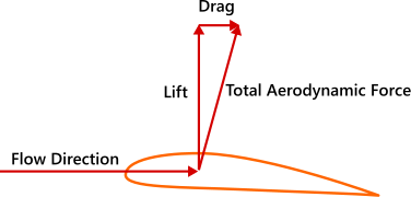
I think it is a good candidate for the article lead, as it defines the two forces the article is about. But the caption could be improved. I'd propose something like, "Lift and drag are the two components of the total aerodynamic force acting on an aerofoil or aircraft".
I suggest "aerofoil or aircraft" advisedly, as l/d is often specified for a given aerofoil over a range of AoA and perhaps also airspeeds, while on the other hand for a sailplane it is typically given for the whole aircraft and dictates the glide angle. This is something the article will eventually need to explain.
— Cheers, Steelpillow (Talk) 14:24, 3 January 2022 (UTC)
- Thanks, Steelpillow. I think this diagram requires a lot of text, because is is not showing directly the topic L/D ratio. I prefer:

- Showing the topic L/D ratio in a typical curve and the influences/causes. The Airfoil diagram can be used below to explain lift and drag. 95.91.246.145 (talk) 15:56, 3 January 2022 (UTC)
- Yes, that's also a useful diagram, but I'd say for later on in the text, once the introductory concepts have been got out of the way and we are ready to introduce coefficients Cl and Cd. I think it is too complex for the lead image. Also, it is not possible to talk sensibly of the l/d ratio until one knows how the l and d are defined, and that is what the simple diagram does. One does not need an aeronautical degree to understand a ratio, it is best stated in the accompanying text. Let's see what others think. — Cheers, Steelpillow (Talk) 16:32, 3 January 2022 (UTC)
- The lift and drag vectors picture is indeed a sound candidate for the main picture, with the improved caption. The curves showing the maximum is too specific for the lead picture, but illustrates well the body.--Marc Lacoste (talk) 16:34, 3 January 2022 (UTC)
- @Marc: Stop the edit-war. Your incompetence is proven above. You fail to see that: starting a new edit-war is a continued aggression. Are you feeling no shame or even responsibility to Wikipedia and your fellow (also IP-) editors?
- I would be glad if i had no reason to say that, but your lack of knowledge seems to have the cause in your lack of understanding, insight and judiciousness. 95.91.246.145 (talk) 07:20, 4 January 2022 (UTC)
- You need to stop WP:personal attacks.--Marc Lacoste (talk) 07:42, 4 January 2022 (UTC)
- Both of you are as bad as each other; you behave abysmally while exhorting your opponent to behave properly. If you don't stop warring I'll take the pair of you to WP:ANEW. My advice to you both is to take five, sit back and let others sort things out; there is an awful lot more wrong with this article that it would be nice to be able to get round to. I shall not warn you again. — Cheers, Steelpillow (Talk) 08:23, 4 January 2022 (UTC)
- I never had personal remarks. I only applied Wikipedia's policies, politely. thanks for not putting me in the same wagon. have a nice day. --Marc Lacoste (talk) 08:33, 4 January 2022 (UTC)
- Both of you are as bad as each other; you behave abysmally while exhorting your opponent to behave properly. If you don't stop warring I'll take the pair of you to WP:ANEW. My advice to you both is to take five, sit back and let others sort things out; there is an awful lot more wrong with this article that it would be nice to be able to get round to. I shall not warn you again. — Cheers, Steelpillow (Talk) 08:23, 4 January 2022 (UTC)
- You need to stop WP:personal attacks.--Marc Lacoste (talk) 07:42, 4 January 2022 (UTC)
- The lift and drag vectors picture is indeed a sound candidate for the main picture, with the improved caption. The curves showing the maximum is too specific for the lead picture, but illustrates well the body.--Marc Lacoste (talk) 16:34, 3 January 2022 (UTC)
- Yes, that's also a useful diagram, but I'd say for later on in the text, once the introductory concepts have been got out of the way and we are ready to introduce coefficients Cl and Cd. I think it is too complex for the lead image. Also, it is not possible to talk sensibly of the l/d ratio until one knows how the l and d are defined, and that is what the simple diagram does. One does not need an aeronautical degree to understand a ratio, it is best stated in the accompanying text. Let's see what others think. — Cheers, Steelpillow (Talk) 16:32, 3 January 2022 (UTC)
Remaining image of a Wright glider[edit]
This image is also the subject of controversy:

My own view is that it does not support the section it is currently in, viz. Examples of L/D ratios, because it shows lift-minus-weight vs drag and not lift alone vs drag. Also, the presence or otherwise of dynamic (acceleration) effects is not clear. Nor can I see any other section it is more suited to. Therefore it should be deleted. What do others think? — Cheers, Steelpillow (Talk) 18:39, 4 January 2022 (UTC)
- The Wright Flyer is listed in the examples (8.3:1). The caption could be changed for your formulation "lift-minus-weight vs drag". The picture seems stabilised, with no dynamic acceleration, photography wasn't instantaneous in 1902.--Marc Lacoste (talk) 19:20, 4 January 2022 (UTC)
- Again, no information about L/D ratio can be inferred from this photo. Bringing it into this article suggests otherwise and is misleading. The tether adds complexity, it does not illustrate the concept or the performance of the glider. And that is even before we bring in considerations of dynamic effects, updrafts etc. which push us way into original research. --Ariadacapo (talk) 18:40, 5 January 2022 (UTC)
- It's not easy to find a photograph illustrating this concept. An other way would be to show a top performing aircraft, eg Eta (glider), but it's not as obvious as the tether (which has many limitations of course). The best way would be with a weightless aircraft (I remember someone inflated a kitesurf kite with helium but it wasn't enough for it to float :) ).--Marc Lacoste (talk) 19:27, 5 January 2022 (UTC)
- The L/D is an abstract idea quantifying one of many aspects of aircraft performance. In this case one picture can’t do a good job at it. Again I strongly disagree, the tether angle is not obviously illustrating it. If you really insist on having photos, ordinary aircraft in flight would be better. The Wright machines are historically significant but not with respect to the topic of this article. -- Ariadacapo (talk) 08:54, 6 January 2022 (UTC)
- The image shows an angle corresponding to an l/d of perhaps 40 or 50. This is impossible for such a primitive design and something else must be going on. Explaining what the image is really showing is just explaining why it is irrelevant here. Including the IP we have a consensus of three against one that the image be removed. I shall do so. — Cheers, Steelpillow (Talk) 09:11, 6 January 2022 (UTC)
- I would say around 10, consistent with the 8.3 wright flyer. Anyway, I replaced it by a picture of an eta glider in flight.--Marc Lacoste (talk) 09:16, 6 January 2022 (UTC)
- It's not easy to find a photograph illustrating this concept. An other way would be to show a top performing aircraft, eg Eta (glider), but it's not as obvious as the tether (which has many limitations of course). The best way would be with a weightless aircraft (I remember someone inflated a kitesurf kite with helium but it wasn't enough for it to float :) ).--Marc Lacoste (talk) 19:27, 5 January 2022 (UTC)
[edit]
Participate if you want. 95.91.246.145 (talk) 08:19, 5 January 2022 (UTC)
- Thank you for letting us know. — Cheers, Steelpillow (Talk) 11:02, 5 January 2022 (UTC)
- Start-Class physics articles
- Mid-importance physics articles
- Start-Class physics articles of Mid-importance
- Start-Class fluid dynamics articles
- Fluid dynamics articles
- Articles with conflicting quality ratings
- C-Class aviation articles
- WikiProject Aviation articles
- Start-Class energy articles
- Unknown-importance energy articles