
User:Krishnavedala/MyStuff
My Stuff
 | This user is a member of WikiProject Electronics, an attempt to provide a standard approach to writing articles about electronics on Wikipedia. If you would like to participate, visit the project page, where you can join the project and see a list of open tasks. |
TODOs[edit]
Synchronous Motors[edit]
Chapter #1[edit]
- As load on the motor increases, Ia increases regardless of excitation.
- For under and over excited motors, the power factor (p.f.) tends to approach unity with increase in load.
- Both with under and over excitation, change in p.f.is greater than in Ia with increase in load.
- With normal excitation, when load is increased, change in Ia is greater than in p.f. which tends to become increasingly lagging.
- Important Points
- The magnitude of armature current varies with excitation. The current has large value both for low and high values of excitation (though it is lagging for low excitation and leading for higher excitation). In between, it has minimum value corresponding to a certain excitation. The variations of I with excitation are known as V curves because of their shape.
- For the same input, the armature current varies over a wide range and so causes the power factor also to vary accordingly. When over-excited, motor runs with leading power factor and with lagging power factor when under-excited. In between, the power factor is unity. The curve for power factor looks like inverted V curve. Also, the minimum armature current corresponds to unity power factor.
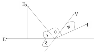
Image: Synchronous Motor-Excitation & Power Factor
Theory
- As per the first point, an over-excited motor can be run with leading power factor. This property renders it extremely useful for phase advancing (and so power factor correction) purposes in the case of industrial loads driven by induction motors and lighting and heating rods supplied through transformers.
- Both transformers and induction motors draw lagging currents from the line. Especially on light loads, the power drawn by them has has a large reactive component and the power factor has a very low value. This reactive component, though essential for operating the electrical machinery, entails appreciable losses in many ways. By using synchronous motors in conjunction with induction motors and transformers, the lagging reactive power required by the latter is supplied locally by the leading reactive component taken by the former, thereby relieving the line and generators of much of the reactive component. Hence, they now supply only the active component of the load current.
- When used in this way, a synchronous motor is called as synchronous capacitor, because it draws, like a capacitor, leading current from the line. Most synchronous capacitors are rated between 20 MVAr and 200 MVAr and many are hydrogen cooled.
Chapter #2[edit]
Principle of Operation:
- Torque acting on the rotor is not unidirectional but pulsating one and due to inertia of the rotor, it will not move in any direction. So, the synchronous motor has got no self starting torque.
- To obtain a continuous torque, the rotor should rotate at synchronous speed given by:
- The angular displacement between the rotor and stator poles &delta is called the torque angle.
- Synchronous motor is able to supply increased mechanical load, not by reduction in speed, but by shift in relative positions of the rotor and rotating magnetic field.
- The maximum value of torque that a motor can develop without loosing synchronism is called the pull-out torque. These values range from 125% to 350% of full load torque values.
- The motor tends to operate at a nearly constant flux or generated voltage, as does the transformer.
- The change in field excitation neither effects the speed of the motor not the output of the motor but does affect the power factor and consequently armature current for constant supply


voltage and constant input power.
- Mechanical power developed in a synchronous motor:
![{\displaystyle P_{mech}={\frac {-E}{Z_{s}}}[cos{\theta }(E-Vcos{\delta })-sin{\theta }Vsin{\delta }]}](https://wikimedia.org/api/rest_v1/media/math/render/svg/7a91ad67a639314faea47294cbb477bbb23ce852)

Synchronous Condensor[edit]
- In large industrial plants, which have a low lagging power factor load, it is often found economica to install a synchronous motor, even though it is not required to drive a load.
- The motor is operated over-excited at no load so that the current drawn by it leads the voltage by nearly 90˚.
- A synchronous motor used in this way is said to float on the line because it has no mechanical output.
- Since the motor operating at no load acts in the same manner as a static capacitor and when operated in this manner, it is called synchronous condensor or synchronous capacitor.
- The synchronous condensor is especially designed so that practically all its rated KVA are available for power factor correction.
- The design of a synchronous capacitor is characterised by its large synchronous reactance and field windings, because its function is to develop zero power factor currents with the least expenditure of power in losses.
- In comparision to a synchronous motor with equal armature voltage and current ratings, a synchronous condensor needs more copper in the field winding to carry the increased field current.
- The synchronous condensor does not require so large shaft and bearing as the synchronous motor as no shaft torque is required.
- The advantage of synchronous condensor over static capacitor is that power factor can very easily be controlled by variation of the field excitation.
Synchronous Phase Modifiers[edit]
- Synchronous condensors are sometimes operated through unity to leading for voltage control. When operated in this manner a synchronous condensor is called synchronous phase modifier or reactor.
- The voltage at the end of a long transmission line can be controlled by installing a synchronous condensor at the end of the t-line.
- Eve nwithout the adjustment of DC excitation, a synchronous motor tendsto maintain voltage constant at the end of transmission line having reactor.
Applications[edit]
- In power houses and substations in parallel to the bus-bars to improve the power factor. For this purpose, they are run without mechanical load on them and over-excited.
- In factories having a large number of induction motors, or other power apparatus operating at lagging power, they are employed to remove the power factor.
- Such motors are also used to regulate the voltage at the end of transmission lines.
- Because of higher efficiency possible, they can be employed advantageously for the loads where constant speed is required.
- The fields of applications of low speed synchronous motors (below 500rpm) are drives such as reciprocating compressors when started unloaded, dc generators, centrifugal and screw type pumps, vacuum pumps and compressors, reciprocating pumps and compressors, constant speed frequency changers, rubber and paper mills, etc..
- Fly wheel is used for pulsating loads.