
File:Rankine cycle layout.png

Size of this preview: 800 × 519 pixels. Other resolutions: 320 × 208 pixels | 640 × 415 pixels | 1,024 × 664 pixels | 1,280 × 830 pixels | 1,850 × 1,200 pixels.
Original file (1,850 × 1,200 pixels, file size: 142 KB, MIME type: image/png)
| This is a file from the Wikimedia Commons. Information from its description page there is shown below. Commons is a freely licensed media file repository. You can help. |
Summary
| Description |
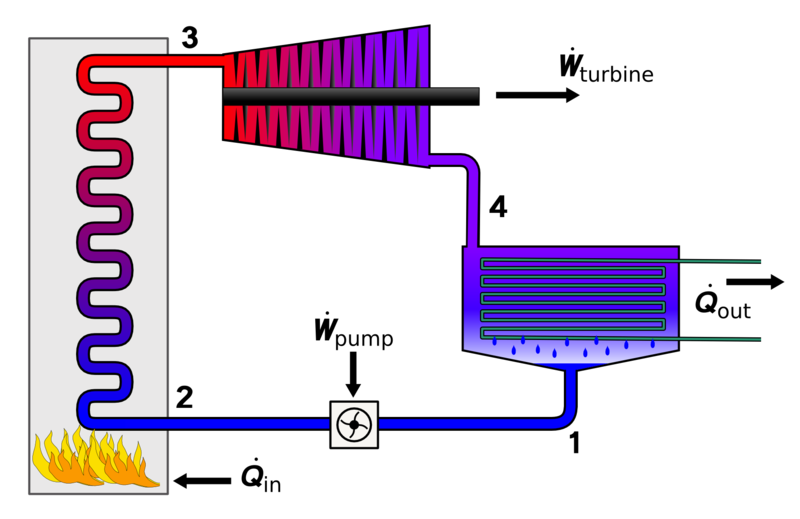
English: Diagram showing the basic layout of a Rankine cycle; Fluid is pumped to high pressure going from state 1 to 2. Heat is added in the boiler by the burning of fuel (although heat can be added by any method) boiling the fluid to state 3. The vapour expands through the turbine dropping significantly in pressure and temperature to state 4. Finally the vapour is condensed back to a liquid and fed back in the pump.
Русский: Структурная схема паросиловой установки с использованием классического цикла Ренкина. 1 – Конденсат рабочего тела после конденсатора; |
| Date | |
| Source | Own work |
| Author | Andrew.Ainsworth at English Wikipedia |
| Other versions |
|


|
File:Rankine cycle layout.svg is a vector version of this file. It should be used in place of this PNG file when not inferior.
File:Rankine cycle layout.png → File:Rankine cycle layout.svg
For more information, see Help:SVG. |
 |
Licensing
Wikipedia (user:andrew.ainsworth) user [[:User:Andrew.Ainsworth:User:{{{3}}}|{{{3}}}]], the copyright holder of this work, hereby publishes it under the following license:

|
Permission is granted to copy, distribute and/or modify this document under the terms of the GNU Free Documentation License, Version 1.2 or any later version published by the Free Software Foundation; with no Invariant Sections, no Front-Cover Texts, and no Back-Cover Texts. A copy of the license is included in the section entitled GNU Free Documentation License. |
| This file is licensed under the Creative Commons Attribution-Share Alike 3.0 Unported license. | ||
| Attribution: Wikipedia (user:andrew.ainsworth) user [[:User:Andrew.Ainsworth:User:{{{3}}}|{{{3}}}]] | ||
| ||
| This licensing tag was added to this file as part of the GFDL licensing update. |
File history
Click on a date/time to view the file as it appeared at that time.
| Date/Time | Thumbnail | Dimensions | User | Comment | |
|---|---|---|---|---|---|
| current | 13:20, 24 June 2009 | | 1,850 × 1,200 (142 KB) | Sv1xv | {{Information |Description={{en|1=Diagram showing the basic layout of a Rankine cycle; Fluid is pumped to high pressure going from state 1 to 2. Heat is added in the boiler by the burning of fuel (although heat can be added by any method) boiling the flui |
File usage
The following pages on the English Wikipedia use this file (pages on other projects are not listed):
Global file usage
The following other wikis use this file:
- Usage on ar.wikipedia.org
- Usage on ast.wikipedia.org
- Usage on bg.wikipedia.org
- Usage on bn.wikipedia.org
- Usage on ckb.wikipedia.org
- Usage on el.wikipedia.org
- Usage on es.wikipedia.org
- Usage on fa.wikipedia.org
- Usage on he.wikipedia.org
- Usage on hi.wikipedia.org
- Usage on hr.wikipedia.org
- Usage on ko.wikipedia.org
- Usage on mr.wikipedia.org
- Usage on ms.wikipedia.org
- Usage on ne.wikipedia.org
- Usage on nl.wikipedia.org
- Usage on no.wikipedia.org
- Usage on pl.wikipedia.org
- Usage on pt.wikipedia.org
- Usage on ro.wikipedia.org
- Usage on ru.wikipedia.org
- Usage on sh.wikipedia.org
- Usage on sl.wikipedia.org
- Usage on sr.wikipedia.org
- Usage on sv.wikipedia.org
- Usage on ta.wikipedia.org
- Usage on tl.wikipedia.org
- Usage on tr.wikipedia.org
- Usage on uk.wikipedia.org
- Usage on ur.wikipedia.org
- Usage on vi.wikipedia.org
- Usage on www.wikidata.org
- Usage on zh.wikipedia.org