
File:Popov receiver.png
Original file (1,918 × 1,699 pixels, file size: 28 KB, MIME type: image/png)
| This is a file from the Wikimedia Commons. Information from its description page there is shown below. Commons is a freely licensed media file repository. You can help. |
Summary
| Description |
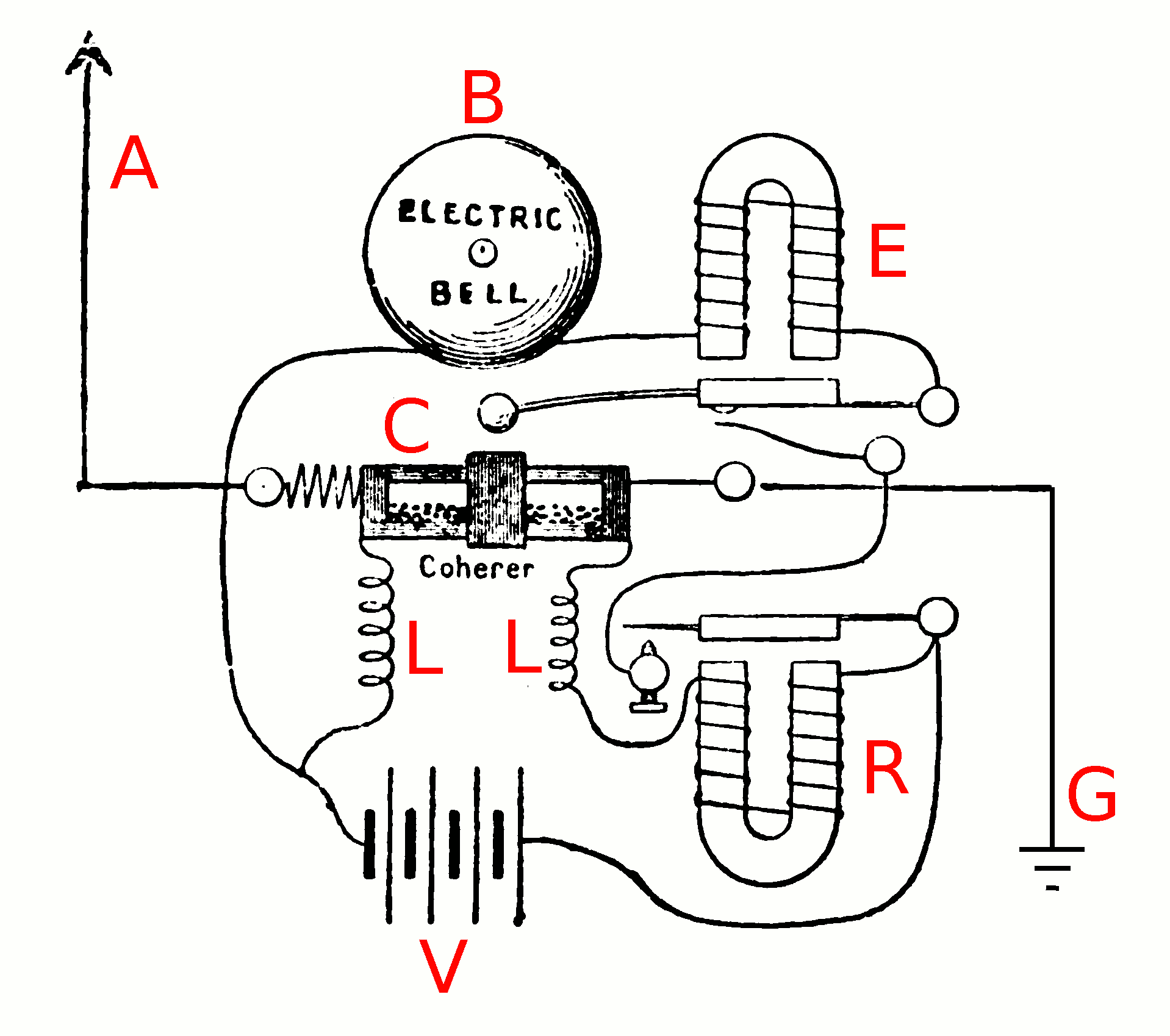
English: Pictorial diagram of the circuit of Alexander Stepanovich Popov's 1895 coherer receiver, one of the earliest radio receivers. Built as a lightning detector, to warn of approaching thunderstorms by detecting the radio pulses from lightning strikes, Popov first demonstrated it before the Russian Physics and Chemical Society in St. Petersburg 7 May 1895 by receiving transmissions from a spark gap transmitter.
The device uses a primitive radio wave detector called a coherer (C), consisting of a glass tube containing metal filings between two electrodes. When radio waves are applied to the coherer electrodes it causes the coherer to become conductive. Before it can receive another signal, the metal filings must be mechanically disturbed by tapping the coherer, to restore it to the high-resistance receptive state. An advantage of Popov's receiver is that the coherer is automatically reset immediately after receiving a signal by tapping the glass tube with the arm of the electric bell used to indicate the arrival of the radio signal. The electrodes of the coherer are connected to a wire aerial (A) and a ground (earth) connection (G). The coherer electrodes are also connected in a second circuit to a battery (V) and a relay (R). When a radio signal from the antenna is applied across the electrodes, it causes the metal filings to become conductive. The current from the battery passes through the coherer and the relay's electromagnet, closing its contacts. This applies current to the bell's electromagnet (E), which pulls it's springy arm over to tap the bell (B). When the arm springs back it taps the coherer, resetting it. The relay is needed because the coherer won't pass enough current to ring the bell by itself. The chokes (L) prevent the impulsive radio noise from the relay's contacts from triggering the coherer again. Alterations to image: added ground symbol, labeled parts in red. |
| Date | |
| Source | Retrieved 9 November 2013 from John Joseph Fahie 1902 A History of Wireless Telegraphy, Dodd, Mead, and Co., New York, p. 205, fig. 35 on Google Books |
| Author | Alexandr Stepanovich Popov |
Licensing
This media file is in the public domain in the United States. This applies to U.S. works where the copyright has expired, often because its first publication occurred prior to January 1, 1929, and if not then due to lack of notice or renewal. See this page for further explanation.
|
 | |
 |
This image might not be in the public domain outside of the United States; this especially applies in the countries and areas that do not apply the rule of the shorter term for US works, such as Canada, Mainland China (not Hong Kong or Macao), Germany, Mexico, and Switzerland. The creator and year of publication are essential information and must be provided. See Wikipedia:Public domain and Wikipedia:Copyrights for more details.
|
File history
Click on a date/time to view the file as it appeared at that time.
| Date/Time | Thumbnail | Dimensions | User | Comment | |
|---|---|---|---|---|---|
| current | 12:03, 10 November 2013 | | 1,918 × 1,699 (28 KB) | Chetvorno | User created page with UploadWizard |
File usage
Global file usage
The following other wikis use this file:
- Usage on ca.wikipedia.org
- Usage on cs.wikipedia.org
- Usage on fr.wikipedia.org
- Usage on hu.wikipedia.org
- Usage on ko.wikipedia.org
- Usage on sq.wikipedia.org