
File:Bandpass Filter.svg

Size of this PNG preview of this SVG file: 600 × 300 pixels. Other resolutions: 320 × 160 pixels | 640 × 320 pixels | 1,024 × 512 pixels | 1,280 × 640 pixels | 2,560 × 1,280 pixels.
Original file (SVG file, nominally 600 × 300 pixels, file size: 26 KB)
| This is a file from the Wikimedia Commons. Information from its description page there is shown below. Commons is a freely licensed media file repository. You can help. |
| Description |
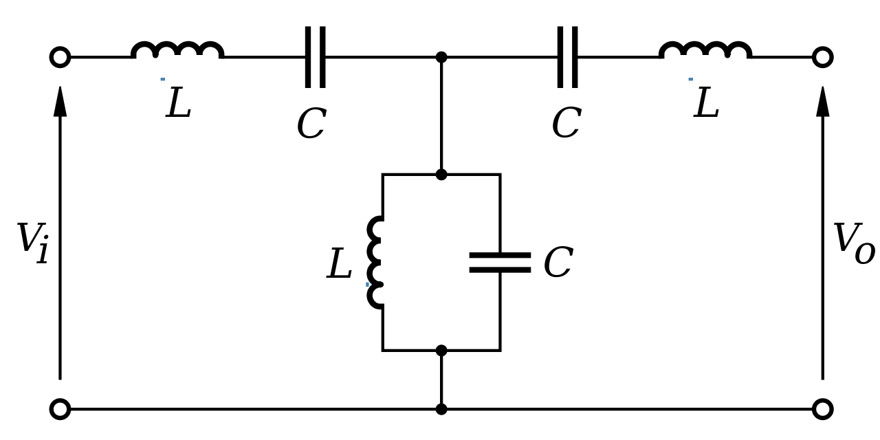
English: A schematic diagram of an example of a band-pass filter, in T-section Cauer topology. This filter is made up of capacitors with capacitance C and inductors of inductance L. |
||
| Date | |||
| Source | Own work | ||
| Author | Inductiveload | ||
| Permission (Reusing this file) |
|
File history
Click on a date/time to view the file as it appeared at that time.
| Date/Time | Thumbnail | Dimensions | User | Comment | |
|---|---|---|---|---|---|
| current | 22:46, 19 October 2008 | | 600 × 300 (26 KB) | Inductiveload | {{Information |Description={{en|1=A schematic diagram of an example of a band-pass filter, in T-section en:Cauer topology. This filter is made up of capacitors with capacitance ''C'' and inductors of inductance ''L''.}} |Source=Own work by uploader |
File usage
The following pages on the English Wikipedia use this file (pages on other projects are not listed):
Global file usage
The following other wikis use this file:
- Usage on ar.wikipedia.org
- Usage on da.wikipedia.org
- Usage on de.wikipedia.org
- Usage on eo.wikipedia.org
- Usage on fa.wikipedia.org
- Usage on ms.wikipedia.org
- Usage on ru.wikipedia.org
- Usage on tr.wikipedia.org
- Usage on uk.wikipedia.org
- Usage on vi.wikipedia.org